Prm-8 connections, Page 6, Program input and output wiring schemes – Oxmoor PRM-8 User Manual
Page 8: Page input wiring schemes
+
–
S
HIGH
LOW
SHIELD
+
–
S
HIGH
LOW
NC
UNBALANCED
UNBALANCED
UNBALANCED
UNBALANCED
UNBALANCED
BALANCED
BALANCED
BALANCED
BALANCED
BALANCED
Page 6
PRM-8 CONNECTIONS
Figure 3.4: Page Input Wiring Schemes
8
7
6
5
4
3
2
1 8
7
6
5
4
3
2
1
PROGRAM OUTPUTS
PROGRAM INPUTS
+
–
S
PAGE INPUTS
+
–
S
LINE
LEVEL
LINE
MIC/LINE
LEVEL
MIC/LINE
LINE
MIC
PUSH
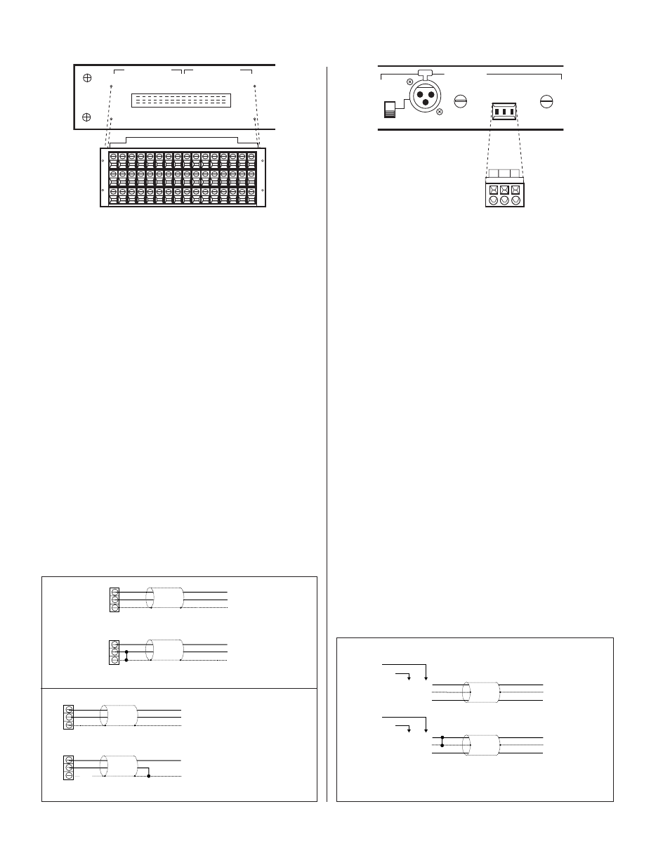
PROGRAM INPUT AND OUTPUT WIRING SCHEMES
(Refer to Figures 3.1 and 3.2)
The diagrams below illustrate the correct wiring of balanced
and unbalanced program inputs and outputs.
PROGRAM INPUT AND OUTPUT CONNECTIONS
(Refer to Figure 3.0)
The PRM-8 Page Module provides connections for eight
program channels. Upon initiation of a page, the page inputs
are routed to any one, or any combination, of these program
channels.
The Program Input and Output connections are made through
a 48-pin screw terminal block mating connector. NOTE: Make
sure that the two mounting screws (shipped with the connector) are
used to secure the 48-pin screw terminal to the enclosure.
1.
PROGRAM INPUTS:
(S) = Shield, (+) = High, (–) = Low,
electronically balanced input, accepts balanced or
unbalanced signals from line-level devices. Nominal input
level is +4 dBu with maximum input level of + 24 dBu.
2.
PROGRAM OUTPUTS:
(S) = Shield, (+) = High, (–) = Low,
electronically balanced output accommodates balanced or
unbalanced lines. Recommended load impedance is 600
ohms or greater. Maximum output level is +26 dBu.
PAGE INPUT CONNECTIONS
(Refer to Figure 3.3)
The PRM-8 Page Module provides connections for two page
inputs. Page inputs are easily routed to any one, or any
combination, of the module's eight program channels.
1.
MIC/LINE:
XLR input, Pin 1 = Shield, 2 = High, 3 = Low,
accepts balanced or unbalanced signals from mic-level or
line-level audio devices.
MIC, LINE: Set switch to MIC position for mic-level or
LINE
position for line-level source.
MIC/LINE LEVEL:
Use a small flat-blade screwdriver to
adjust the MIC/LINE input for various input signal levels.
2.
LINE:
(S) = Shield, (+) = High, (–) = Low, accepts balanced
or unbalanced signals from line-level audio devices. The
connections are made through a 3-pin cage-clamp
connector. The cage-clamp spring clamps the wire
providing quick and easy termination.
LINE LEVEL:
Use a small flat-blade screwdriver to adjust the
LINE input for various input signal levels.
Figure 3.3: Page Inputs View
Figure 3.0: Program Inputs and Outputs View
PAGE INPUT WIRING SCHEMES
(Refer to Figure 3.4)
The diagram below illustrates the correct wiring of balanced
and unbalanced page inputs.
–
S
+
3
1
2
LINE IN
MIC/LINE IN
–
S
+
3
1
2
LINE IN
MIC/LINE IN
LOW
NC
HIGH
LOW
SHIELD
HIGH
BALANCED
BALANCED
BALANCED
BALANCED
BALANCED
UNBALANCED
UNBALANCED
UNBALANCED
UNBALANCED
UNBALANCED
+
–
S
LOW
HIGH
+
–
S
SHIELD
HIGH
LOW
NC
BALANCED
BALANCED
BALANCED
BALANCED
BALANCED
UNBALANCED
UNBALANCED
UNBALANCED
UNBALANCED
UNBALANCED
Figure 3.2: Program Output Wiring Schemes
Figure 3.1: Program Input Wiring Schemes
NOTE:
The unbalanced
output configuration
is valid ONLY if the
Balanced/Unbalanced
output jumper block
has been set to the
unbalanced position.
See page 6, Figure 2.4.