Prm-8 set-up, Page 4, Prm-8 program channels – Oxmoor PRM-8 User Manual
Page 6: Pa-422 address
Page 4
PRM-8 SET-UP
PRM-8 SET-UP OVERVIEW
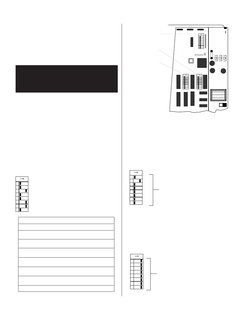
(Refer to Figure 2.1)
The PRM-8 has three internal dip switches that may be used to
configure its operation for different system requirements. Before
installing the PRM-8, refer to the switch function description
below to determine the switch positions best suited to your
system requirements. Refer to page 10 for a typical control panel
configuration and its operation.
OXMOOR CORPORATION
MADE IN USA
PRM-8
COPYRIGHT 1994
PCB # 1300129
REVISION A
SW2
SW3
SW1
230
ON
1234
5678
ON
1234
5678
ON
1234
5678
SW6
POWER LED
SW 1
SW 3
SW 2
AC POWER TRANSFORMER
SW3 SET-UP PROCEDURE
(Refer to Figure 2.3)
SW3 allows individual channels to NOT receive the All
Page source. Those channels switched OFF will continue to
mute and ramp the program source during an All Page, but
will not receive the All Page source.
SW3
ON
1234
5678
1
2
3
4
5
6
7
8
PRM-8 Program Channels
Figure 2.3: Factory Set-Up for SW3
SW2
ON
1234
5678
1
2
4
8
16
32
64
128
PA-422 Address
Figure 2.2: Factory Set-Up for SW2
SW2 SET-UP PROCEDURE
(Refer to Figure 2.2)
Switch SW2 determines the PA-422 address. When the PA-
422 port is to be used, the PRM-8's PA-422 address should be
set to the same address as the controlling device. PA-422
requires that a device's address be between 1 and 250.
SW2:
Shipped from factory with
PA-422 set to address 2.
Figure 2.1: SW1, SW2 and SW3 Location on Printed Circuit Board
SW3:
Shipped from factory with all
channels set to receive the All
Page source (all channels ON).
1
* Off
= Not used, set to Off position
2
* Off
= Not used, set to Off position
3
Off
= Zone Page selection is NOT stored
* On
= Zone Page selection is stored
4
* Off
= Channel Select set for MAINTAINED closures
On
= Channel Select set for MOMENTARY closures
5
* Off
= Mic/Line input NOT used as All Page
On
= Mic/Line input used as All Page
6
Off
= Line input NOT used as All Page
* On
= Line input used as All Page
7
Off
= Mic/Line input NOT used as Zone Page
* On
= Mic/Line input used as Zone Page
8
* Off
= Line input NOT used as Zone Page
On
= Line input used as Zone Page
*
Indicates factory settings.
Note:
The Zone Page Clear function can be used only
if the Control Port is set for MOMENTARY
operation (#4 ON).
SW1:
Shipped from factory configured as shown.
Figure 2.0: Factory Set-Up for SW1
SW1
ON
1234
5678
CAUTION!
Hazardous voltages are present inside the chassis.
Before opening the case to gain access to the printed
circuit board, always remove the power from the unit by
disconnecting the AC power cord.
If changes are required:
1. Disconnect the AC power cord.
2. Remove the screws that secure the top cover and set the cover
aside.
3. Use the front panel Power LED and the AC Power
Transformer as reference points to locate SW1, SW2 and SW3
which are located on the component side of the PRM's printed
circuit board
.
SW1 SET-UP PROCEDURE
(Refer to Figure 2.0)
Switch SW1 determines if: A manual Zone Page Clear line is to
be used; The system is to store the Zone Page selections after a
zone page; The Channel Select is to operate with momentary or
maintained closures; The Page inputs are to be used as All Page,
Zone Page or both
.