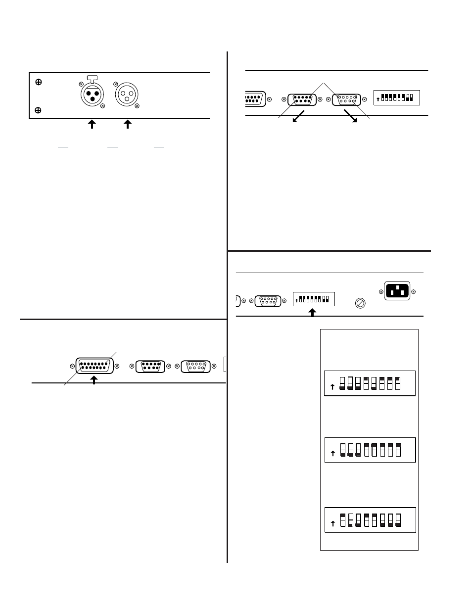
Appendix a: hardware interconnection details, Figure a4: address select switch, Figure a3: pa-422 in & out connectors – Oxmoor DEQ-1 User Manual
Page 26: Figure a1: audio in & out connectors, Figure a2: preset select connector, Page 24, High, Shield, Low pin number
Page 24
UT
C
S
POWER
FUSE
PA-422 INPUT
PA-422 ADDRESS
128
64
32
16
8
4
2
1
ON
PA-422 OUTPUT
T SELECT
PA-422 INPUT
PA-422 ADDRESS
128
64
32
16
8
4
2
1
ON
Figure A4: ADDRESS SELECT SWITCH
FACTORY SETUP:
The DEQ-I & DEQ-
II are shipped from
the factory with the
PA-422 ADDRESS
set to 1.
Figure A3: PA-422 IN & OUT CONNECTORS
1 ........ To DSR +
2 ........ To DSR -
3 ........ No Connection
4 ........ To RXD +
5 ........ To RXD -
6 ........ From DTR +
7 ........ From DTR -
8 ........ From TXD +
9 ........ From TXD -
1 ............ DSR +
2 ............ DSR -
3 ............ No Connection
4 ............ RXD +
5 ............ RXD -
6 ............ DTR +
7 ............ DTR -
8 ............ TXD +
9 ............ TXD -
Pin 1
PA-422 OUTPUT
Female Connector
PA-422 INPUT
Male Connector
Pin 9
Pin 9
NOTE: PA-422
requires that a
device's address
be between 1 and
250. Address 0,
251, 252, 253, 254,
and 256 are
illegal.
Figure A1: AUDIO IN & OUT CONNECTORS
APPENDIX A: HARDWARE INTERCONNECTION DETAILS
The output may be set for either balanced (push-pull) or
unbalanced operation. In the unbalanced configuration,
pin 3 of the output connector is grounded, and the maxi-
mum output level drops by 6 dB.
To operate the output unbalanced, you must follow this
procedure; Remove the unit's top lid. Locate the configu-
ration jumper block next to the output connector. The
jumper is factory-installed in the balanced position.
Observing the positions marked on the circuit board,
remove the jumper and reinstall it in the unbalanced
position.
On the output XLR, IN THE UNBALANCED MODE
ONLY, use pin 2 as "HOT" and pin 3 as "COMMON.” Pin
1 is to be used as "SHIELD.”
PIN 2 POSITIVE ON ALL
AUDIO CONNECTORS
OXMOOR
MADE IN USA BY
OXMOOR CORPORATION
BIRMINGHAM, ALABAMA
INPUT
PUSH
OUTPUT
High
2
1
Shield
3
Low
Pin Number
PA-422 OUTPUT
PRESET SELECT
E ON ALL
NECTORS
PA-422 INPUT
O
Figure A2: PRESET SELECT CONNECTOR
PRESET SELECT
Female Connector
Pin 1
Pin 15
1 ................... Preset 1
2 ................... Preset 2
3 ................... Preset 3
4 ................... Preset 4
5 ................... Preset 5
6 ................... Preset 6
7 ................... Preset 7
8 ................... Preset 8
9 ................... Mute
10 ................. Tally 0, LSB (1's)
11 ................. Tally 1, BIT (2's)
12 ................. Tally 2, MSB (4's)
13 ................. +5 VDC
14 ................. Common
15 ................. Common
Pin Number
Function
Pin
Function
Pin
Function
128 64 32 16 8 4 2 1
PA-422 ADDRESS
ON
16+8+4+2+1 =31
128 64 32 16 8 4 2 1
PA-422 ADDRESS
ON
128 64 32 16 8 4 2 1
PA-422 ADDRESS
ON
128 + 16 + 8 = 152
16 + 4+2+1 =23
EXAMPLES