Vectronics VEC-121K User Manual
Page 12
VEC-121K Owner's Manual
Crystal Radio Set Kit
10
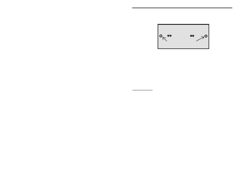
Mounting hole
Mounting hole
! Now, make sure that the two screw pilot holes on the pine board for
mounting the coil form are correct. Refer to the drawings in the manual that
show the placement for the Fahnstock clips and coil form. Temporarily
mount the coil in its proper location using two Phillips head screws. You do
not need to fully tighten the screws, we are just checking to see that things
fit properly.
Important Note: You will need to use a screwdriver with a long shaft (about
three inches) for these two screws because of the large diameter of the coil
form.
! If the coil form mounting holes align properly with the breadboard’s
mounting holes, you may remove the coil and return the screws to the parts
bag. If things don’t match up just right, you will have to mark the correct
position for the breadboard pilot hole with a pencil, and remove the coil.
Make a new pilot hole by using the hammer and finishing nail to make a
small indentation to start the screw. Run a screw into the pilot hole until the
head reaches the board surface. Remove the screw and return it to the parts
bag.
This completes Phase 1. There should be eight screw holes in the pine
breadboard at this point. If so, the mounting holes have been properly located,
marked, and the screw holes are ready for parts installation!
If you haven’t already done so, this is an excellent time to stain the board (if you
are planning to do so).
We are ready to begin Phase 2.