Vectronics VEC-121K User Manual
Page 23
VEC-121K Owner's Manual
Crystal Radio Set Kit
21
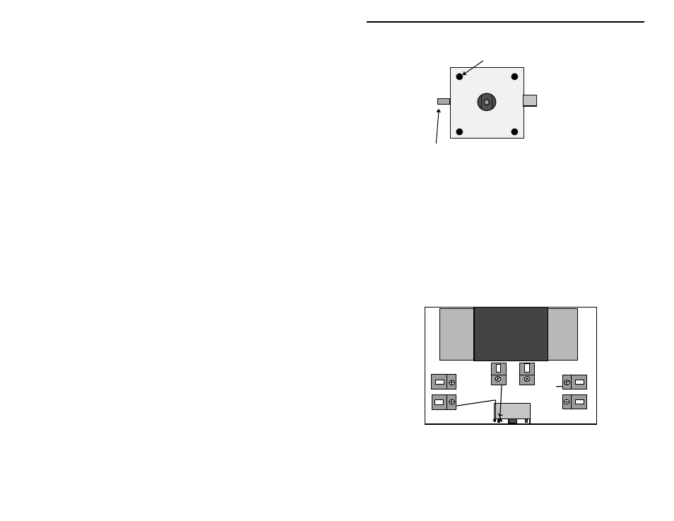
Stator
stud
Rotor lug
(narrow)
This is the correct orientation for installing the capacitor. Note that the
narrower rotor lug must be at the left hand side!
Variable capacitors have two sets of plates. One set of plates remain stationary,
and are called the “stator” plates. The tuning shaft is attached to another set of
plates that rotate as the shaft is turned. They are called the “rotor” plates. As
the shaft is turned, the plates are either meshed or unmeshed, changing the
capacitance value. This is how the tuning capacitor works.
The tuning capacitor will be mounted at the front center of the breadboard using
the double-sided foam tape. The remaining enamel wire lead coming from the
GND Fahnstock clip will be connected to the narrow rotor lug terminal on the
tuning capacitor. The remaining enamel wire lead from the DET1 Fahnstock
clip will be connected to the round stator stud on the front of the capacitor.
The above drawing shows how the wires will be routed to the tuning capacitor
connections.
Connecting the stator lead