Vectronics VEC-121K User Manual
Page 24
VEC-121K Owner's Manual
Crystal Radio Set Kit
22
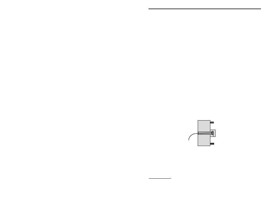
! Temporarily place the tuning capacitor as shown in the drawing. Be sure the
narrowest stator lug is at the left hand side!
! Cut the free enamel wire lead from the GND clip to a length of five inches.
! At the end of the wire, remove 2” of insulation.
! Route the enamel wire from the GND clip so it reaches to the capacitor
body. At that point, the wire goes up to the middle of the capacitor, and
then makes another sharp bend towards the front of the board.
Study how the capacitor is made. If you look into the capacitor through its clear
plastic housing, you can see how the narrow rotor lug continues to the rear of the
capacitor. At that point, there is a tiny opening in the plastic capacitor housing.
! Take the wire from the GND clip and insert it into this capacitor opening.
Carefully feed the wire so it passes through the capacitor body (it will be
between the plastic housing and narrow metal strap) and finally emerges at
the front end of the capacitor.
! Continue feeding the wire until 1” of bare enamel wire clears the front
opening in the capacitor.
! Using your long nose pliers, carefully wrap the enamel wire around the
narrow rotor lug until two or three full turns are made. Trim off the excess
wire.
! Gently, but firmly, squeeze the turns wrapped around the rotor lug, using the
long nose pliers, until they are compressed tightly--making a good, tight
electrical connection.
Important Note: If for some reason the narrow rotor lug is damaged while trying
to attach the lead, use the wider rotor lug as an alternate connection point.
Making the stator connection