Vectronics VEC-121K User Manual
Page 27
VEC-121K Owner's Manual
Crystal Radio Set Kit
25
! Using the dispenser, allow a small drop of contact adhesive to flow into the
gap and onto the threaded portion of the extension. Quickly screw the
extension back into the tuning capacitor to close the gap. If you are using
model airplane cement, unscrew the shaft extension, and lightly smear a
small amount of glue over the threads. Quickly screw the extension back
into the capacitor shaft.
! Allow time for the glue to harden.
! Using a small screwdriver or hex tool, install the tuning knob on the shaft
extension.
This completes the construction of the VEC-121K crystal set receiver.
TESTING AND ALIGNMENT
1. Turn the capacitor shaft in a counter clockwise direction until the stop is
reached.
2. Loosen the tuning knob set screw, and align the tuning indicator on the knob
so it corresponds to the 9 o’clock position.
3. Tighten the set screw.
4. Verify that the knob indicator properly corresponds to the capacitor stops at
the 9 and 3 o’clock positions.
OPERATING INSTRUCTIONS
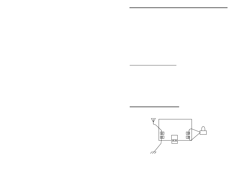
1. Use the hookup shown in the following diagram to make the antenna (aerial),
ground, and earphone connections.
earphone
ground
aerial
Tuning knob
2. Connect the earphone wires to the Fahnstock clips at the right hand side of
the radio.