Vectronics VEC-1220K User Manual
Page 22
VEC-1220K/1230K/1240K/1280K Owner's
Manual
20
! ! 1. Locate two (2) DPDT push-button switches (six pins). Install one of
these at SW1, making sure the switch pins are fully seated and the
switch body is level. Solder in place.
! ! 2. Install the second DPDT push-button switch at SW2.
! ! 3. Locate two (2) RCA PC mounted jacks. Install one of these at J3,
making sure the three metal tabs are seated all the way into the board.
Solder the tabs and center-pin.
! ! 4. Install the second RCA jack at J4 and solder.
! ! 5. Locate the 3.5 mm mini-phone jack. Install at J1, making sure the
plastic case is square to the edge of the PC board and flat against its
surface. Solder all pins.
! ! 6. Locate the 2.1 mm DC power jack. Install at J2, seating the case flat
against the surface of the PC board. Twist each solder tab slightly to
secure the jack place, and solder all three.
Find the plastic-encased variable capacitor. This is the transmitter's VXO tuning
control (C5).
Locate the small strip of double-sided tape. Also, find two of the heavy-gauge
leads removed from the 1N4007 diodes. These items will be used to secure C5
in place.
! ! 7. Using scissors or a hobby knife, cut a 1/2" by 3/4" square of double-
sided tape. Install this within the box printed at C5 on the PC board
(see diagram).
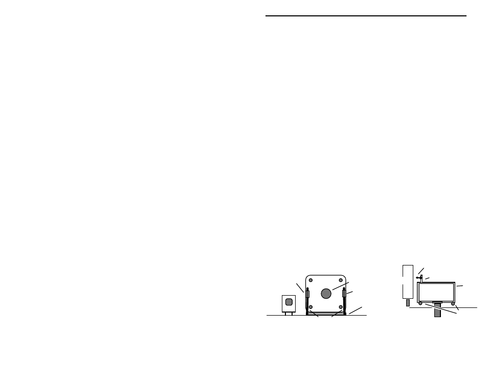
! ! 8. To orient the variable capacitor for installation, use the following
diagram. There should be a ground tab to the left and right of the
shaft. At the rear of the cap, a solder tab will protrude from the case at
lower left. When the cap is positioned as shown, press it down onto
the tape to secure it in place.
SW2
VXO Capacitor
Heavy Leads
Shaft
Double-sided Tape
VXO
Capacitor
C5 Connection
Tab
Tape
Ground Tab
Ground Tab
Ground
Tabs
SW2