Vectronics VEC-483K User Manual
Page 10
VEC-483K Owner’s Manual
Voice Activated Tape Recorder Switch
10
# # 21.$Locate the tie-wrap and install as shown.
Your kit has two (2) min-phono jacks. The larger of the two is a 3.5 mm stereo
jack, and the smaller is a 2.5 mm mono jack. When installing jacks, make sure
the case sets firmly against the PC board surface before soldering.
# # 22.$Install the 3.5 mm jack (larger) at J1 and solder.
# # 23.$Install the 2.5 mm jack (smaller) at J2 and solder.
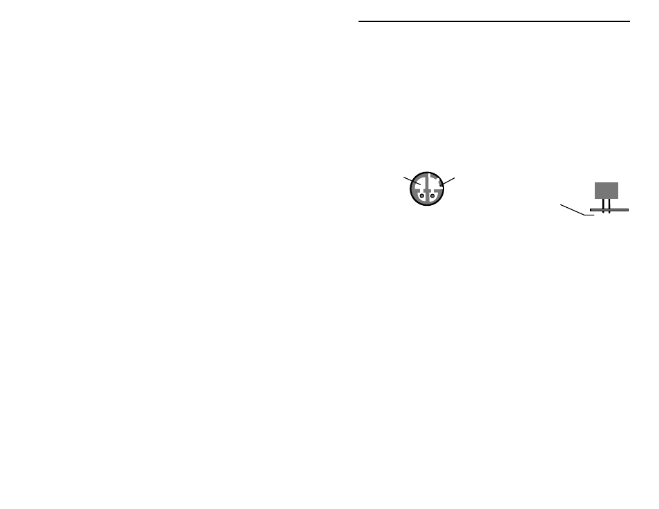
Finally, locate the electret condenser microphone element (MIC1) and observe
the leads. One is grounded to the case by a bridge of metal, while the other is
not. The grounded lead must correspond with the groundplane mounting hole on
the PC board.
Space element above board
so leads protrude
about .1" through
PC board.
Ground Side
"Hot" Side
Element
When positioning the mic element, space as far as possible above the surface of
the PC board. Leads should protrude only enough to ensure a good solder
connection.
# # 24.$Observing polarity, install the electret mic element at MIC1 and solder
in place.
This concludes construction of your VEC-483K Voice-Activated Tape Switch.
Before moving on, give your kit a thorough QC (quality control) inspection.
This will help you discover accidental assembly errors that might prevent it from
working properly--or that might cause damage to sensitive parts when you apply
power. Follow this procedure:
1. Compare parts locations with the parts-placement diagram. Was each part
installed where it is supposed to be? Was the correct value used? Start at
one side of the board and work your way across in an organized pattern.
2. Inspect the solder side of the board for cold-solder joints and solder bridges
between tracks or pads. Use a magnifying glass to obtain a clear view of the
track area. If you suspect a solder bridge, hold the board in front of a bright
light for a better view. All joints should be smooth and shiny, indicating
good solder wetting and flow. Resolder any beaded or dull-appearing
connections. Also, check the front-panel jacks, switches, and connectors for
defective solder connections.
3. Finally, check electrolytic capacitors and diodes for correct polarity. Does
the plus (+) polarity symbol on the part agree with the pictorial and with the