Vectronics VEC-483K User Manual
Page 9
VEC-483K Owner’s Manual
Voice Activated Tape Recorder Switch
9
Also, when soldering, make sure the socket remains flat against the board
surface.
# # 16.$Find the 8-pin IC socket. Orient to U1, install, and solder all pins.
Next, align the LM358 IC with the socket, matching its key with the socket key.
When you install, press in slowly--making sure all pins go into the socket holes
and none fold over under the device.
# # 17.$Observing the key, install the LM358 at U1.
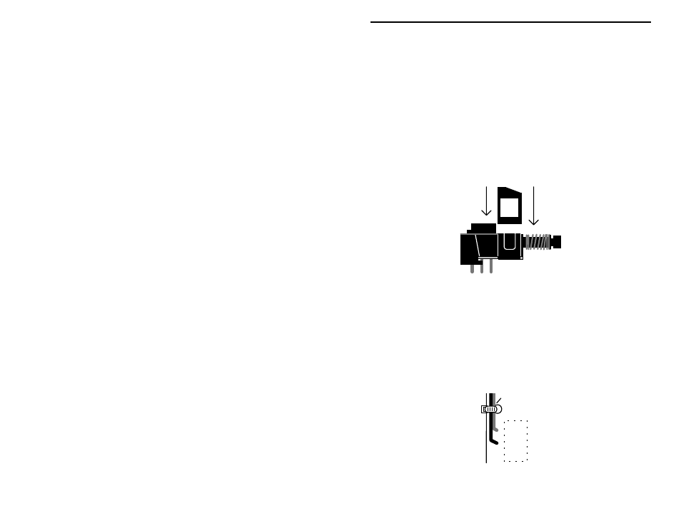
Your kit contains a miniature DPDT switch. Some versions require installation
of a plastic clip-on support at the front of the switch body. This piece relieves
stress on the pins and ensures level seating during installation. If your parts kit
contains this piece, install as shown:
# # 18.$Install the DPDT mini power switch at SW1
Locate the 9-V battery snap clip, and note the red+ lead and black- lead.
# # 19.$Install the red lead at BAT1 (+) and solder.
# # 20.$Install the black lead at BAT1 (-) and solder.
Find the oversized hole slightly to the rear of the BAT1 connections. The plastic
tie-wrap supplied with your kit will be installed here to bind the two battery
leads to the PC board. This will help prevent lead breakage later on.
+
-
SW1
Tie-wrap