Vectronics VEC-483K User Manual
Page 8
VEC-483K Owner’s Manual
Voice Activated Tape Recorder Switch
8
# # 10.$Install 1 uF at C5 and solder.
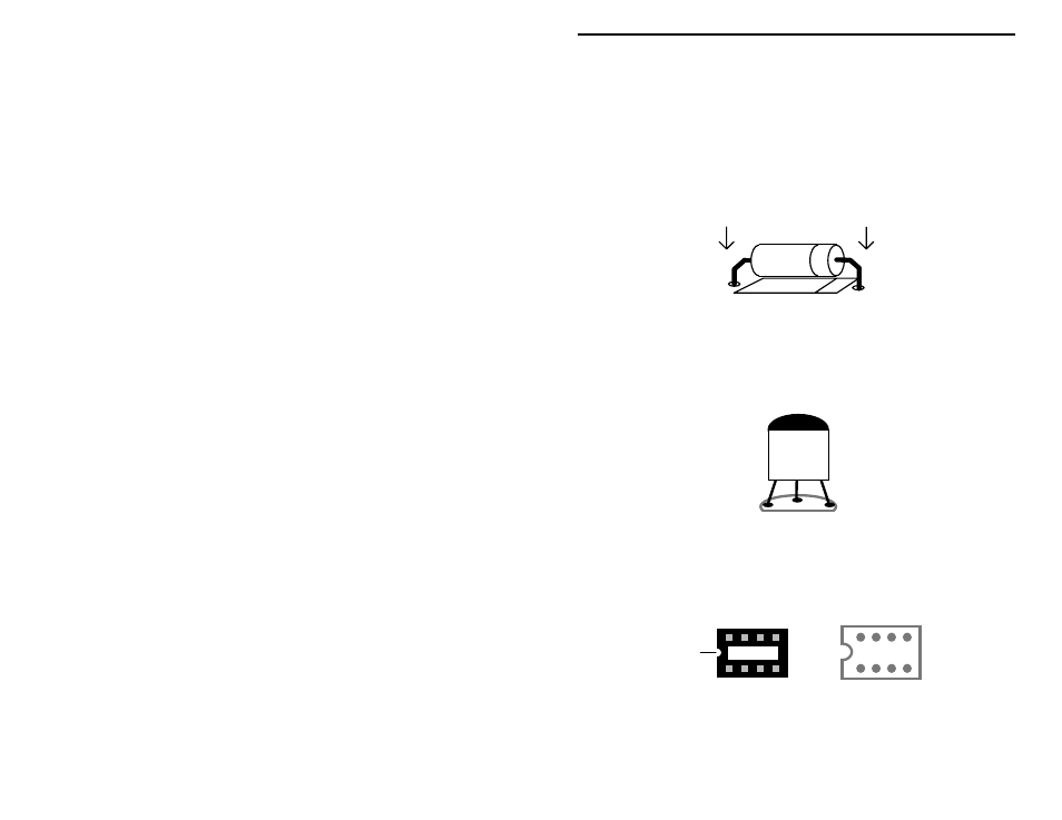
Locate two (2) 10-uF electrolytic capacitors. Observing polarity:
# # 11.$Install 10 uF at C2 and solder.
# # 12.$Install 10 uF at C3 and solder.
Now, find two (2) 1N4148 silicon diodes (glass body). Like capacitors, diodes
are polarized devices that must be installed correctly. Always look for the
banded end when installing--and align this with the banded end shown on the PC
layout.
# # 13.$Install a 1N4148 at D1 and solder.
# # 14.$Install a 1N4148 at D2 and solder.
Locate the 2N7000 plastic transistor. Like the electrolytic caps, transistors must
be oriented correctly to work properly.
2N7000
# # 15.$Install the 2N7000 FET at Q1 and solder.
The ICs in your kit will be installed in a IC socket. Like the IC itself, the socket
is keyed at one end to indicate proper positioning. During installation, orient the
socket so the notch corresponds to the key on the PC layout.
Key
Key
When installing the socket, make sure all pins enter the mounting holes and
appear on the opposite side of the PC board (it's easy to fold one or more under).