Vectronics VEC-483K User Manual
Page 7
VEC-483K Owner’s Manual
Voice Activated Tape Recorder Switch
7
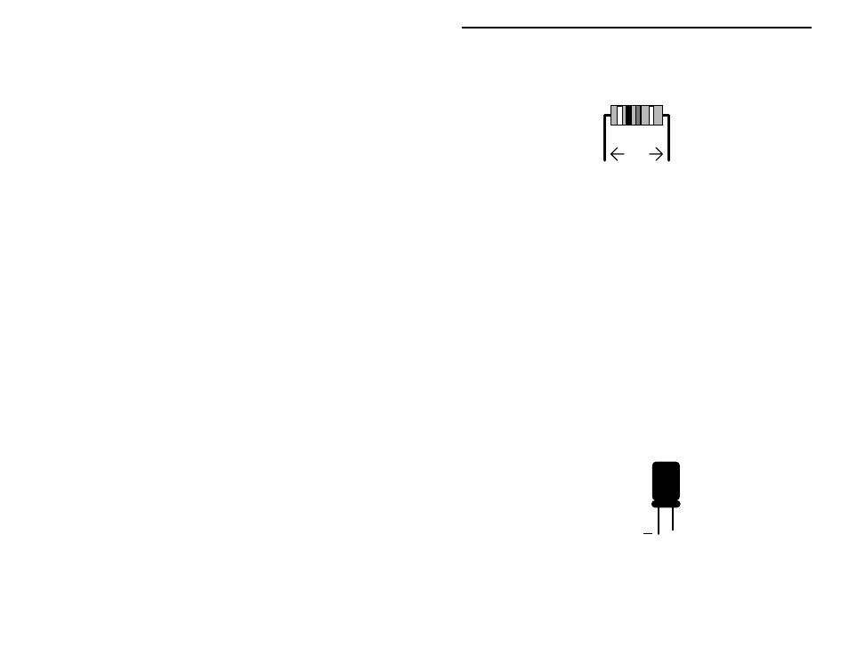
This kit has 5 fixed-value resistors. Mount these now, starting with the smallest
value and moving to the largest. Before mounting each one, carefully bend both
leads close to the resistor body to form right-angles, as shown below:
.4"
Locate two (2) 1K resistors (brown-black-red).
# # 1.$Install 1K at R3 and solder.
# # 2.$Install 1K at R4 and solder.
Locate two (2) 10-K resistors (brown-black-orange).
# # 3.$Install 10 K at R1 and solder.
# # 4.$Install 10 K at R2 and solder.
# # 5.$Find the 47-K resistor (yellow-violet-orange). Install at R6 and solder.
The next two (2) items are 500-K trimpots (black, screw adjustment in the
center, 3 pins). When you install each trimpot, make sure it is seated firmly
against the PC board with all three leads protruding.
# # 6.$Install a 500-K trimpot at R7 and solder.
# # 7.$Install a 500-K trimpot at R8 and solder.
There are five electrolytic capacitors in your kit. Electrolytic caps are
polarized and must be installed the correct way in order to work. Each
capacitor's plus (+) mounting hole is marked on both the circuit board and parts
placement diagram. If the markings on the capacitor body are unclear, the plus
(+) lead is always the longer of the two.
+
Plus Lead
Locate three (3) 1-uF electrolytic capacitors. Observing polarity:
# # 8.$Install 1 uF at C1 and solder.
# # 9.$Install 1 uF at C4 and solder.