AMETEK Compact i/iX Series User Manual
Page 35
User Manual
Compact i/iX Series
AMETEK Programmable Power
California Instruments
35
3.5 AC Input Wiring - INPUT
AC input connections are to be made directly to the input terminal block. The AC input terminal block is
located on the right hand side on the back of the chassis (when facing the back of the unit). It is
label
ed “AC INPUT”.
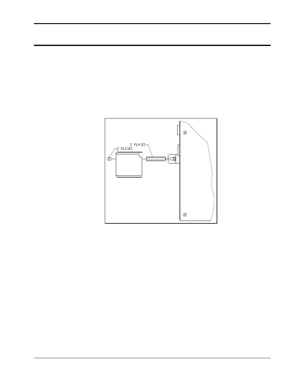
Before connecting the input wiring, the AC input safety cover (P/N 6005-214-1) stand-offs must be
installed. The two stand-offs and screws required to mount the safety cover are provided in the ship kit
(envelope) that comes with the AC power source. Screw the stand offs on to the AC input terminal strip
mounting screws (top and bottom of terminal block. Attach the safety cover to the stand offs using the
provided screws after connecting the AC input wiring.
For Series II units, the AC input line cord breaks out to the right. Refer to Figure 3-3 for Series II units.
Figure 3-3: AC Input safety cover installation for Series II
– Viewed from top.