AMETEK Compact i/iX Series Software Manual User Manual
Page 164
User Manual
– Rev H
California Instruments
164
Avionics Software
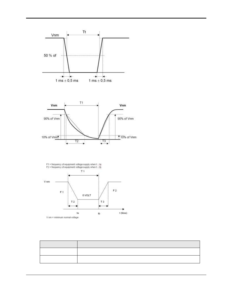
Switching Transients conform Figure B (Rev D) or Figure 1.2 (Rev E). The T1, T2 and T3 values are
shown on screen in the table above the graph. Each permutation shown is repeated one time with a 1
second delay (default) between transients
Table 2 (Rev D) or Table 1.3 (Rev E) transients with roman numerals I through VI are supported as
well by selecting Figure B, Table 2. F1 and F2 represent the test frequencies before and after the
transient.
Controls
The following controls and displays are available in this window:
Control / Display
Description
Start button
Start selected transient test. This button will be disabled while a test is running
and re-enabled at the end of a test.
Abort button
Aborts a test in progress. This button will be disabled unless a test is running
and enabled as soon as a test is started.