AMETEK DLM 600W Series User Manual
Page 66
DLM 600W Series
M362161-01 K
4-8
4.4.1
Voltage–Source Programming of Output Voltage
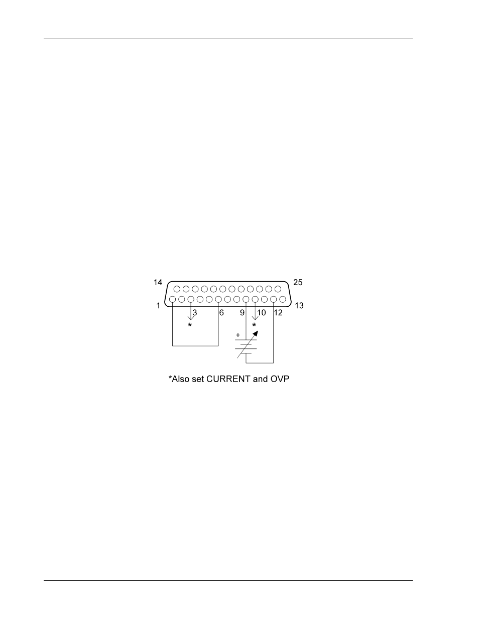
Refer to Figure 4-3 for setting up voltage–source programming of the output voltage.
1.
Set Position-8 of the SETUP switch to OFF for 0–5 VDC programming range.
2.
Set Position-8 of the SETUP switch to ON for 0–10 VDC programming range.
3.
Connect the external programming voltage source to the REMOTE ANALOG
INTERFACE connector, with positive to Pin-9 and negative to Pin-12.
4.
Program the other parameters to the desired limit values: CURRENT
PROGRAMMING INPUT, Pin-10, and the OVP PROGRAMMING INPUT, Pin-3,
with respect to Pin-12. AUXILIARY 5VDC OUTPUT, Pin-15, could be used for
full–scale programming.
NOTE: Step 4 is mandatory. The power supply will not work properly without it.
5.
Connect Pin-1, ANALOG–CONTROL, of the REMOTE ANALOG INTERFACE
connector to Pin-6.
Figure 4-3. Voltage–Source Programming of Output Voltage