AMETEK DLM 600W Series User Manual
Page 71
Advertising
DLM 600W Series
M362161-01 Rev J
4-13
4.4.6
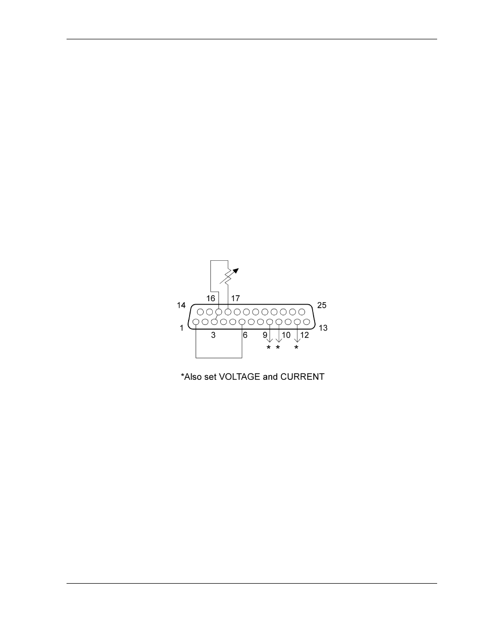
Resistance Programming of OVP
Refer to Figure 4-8 for setting up resistance programming of OVP.
1.
Set Position-6 of the SETUP switch to OFF for 0–5 VDC programming range.
2.
Connect the external resistance, 0–5 k
, to the REMOTE ANALOG INTERFACE
connector, from Pin-17 to Pin-16.
3.
Connect a jumper from Pin-16 to Pin-3.
4.
Program the other parameters to the desired limit values: VOLTAGE
PROGRAMMING INPUT, Pin-9, and the CURRENT PROGRAMMING INPUT,
Pin-10, with respect to Pin-12. AUXILIARY 5VDC OUTPUT, Pin-15, could be
used for full–scale programming.
5.
Connect Pin-1, ANALOG–CONTROL, of the REMOTE ANALOG INTERFACE
connector to Pin-6.
Figure 4-8. Resistance Programming of OVP
Advertising