3 making the connections, 4 connecting single loads, Making the connections -12 – AMETEK DLM Series User Manual
Page 36: Connecting single loads -12
Installation
DLM-E 3kW & 4kW Series Power Supplies
2.8.3
Making the Connections
Load connections to the power supply are made at the positive and negative output terminals
(or bus bars) at the rear of the power supply. See Figure 2–2. The power supply provides three
load wiring mounting holes on each bus bar terminal, as specified in the following table. The
small holes can be used for local sense lines.
Load Wiring Mounting Holes
Diameter
Hardware Size
One (1) per terminal
0.312"
1/4" (5/16" for 8V and 16V models)
One (1) per terminal
#6–32 Screw
0.32" OD (for 150V–600V models)
Two (2) per terminal
0.201" on 0.5" centers
#10 or smaller
CAUTION!
When making connections to the bus bars, provide support when tightening
hardware to prevent bending bus bars. Ensure that the mounting hardware at
each terminal and wiring assembly is placed to avoid touching the other
terminal and shorting the power supply output. Heavy connecting cables
must have some form of strain relief to avoid loosening the connections or
bending the bus bars.
CAUTION!
If unit is not installed in a rack, care should be taken to protect personnel
from contact with output bus bars.
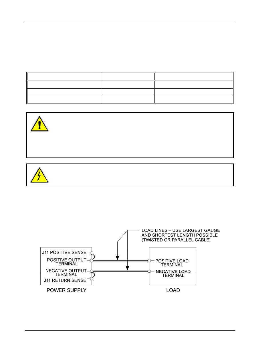
2.8.4
Connecting Single Loads
Figure 2–4 and Figure 2–5 show recommended load and sensing connections for a single load.
Local sense lines shown are default J11 connections. Refer to Section 3.3.1 Connecting
Remote Sense Lines for more information about the sense line shield.
Figure 2–4. Single Load with Local Sensing (Default)
(Local sense lines shown are default J11 to busbar connections)
2-12
M362000-01 Rev E