2 local programming mode operation, Local programming mode operation -3, Figure 3–2. local mode default configuration -3 – AMETEK DLM Series User Manual
Page 41
DLM-E 3kW & 4kW Series Power Supplies
Basic Operation
3.2.2
Local Programming Mode Operation
Units are shipped from the factory configured for local programming mode operation. In local
programming mode:
•
Output voltage and current limit settings are adjusted with the front panel controls.
•
The sense point of the supply is at the output terminals.
•
The front panel OVP potentiometer determines the OVP set point.
See Section 4.4 Using Over Voltage Protection (OVP) for the adjustment procedure.
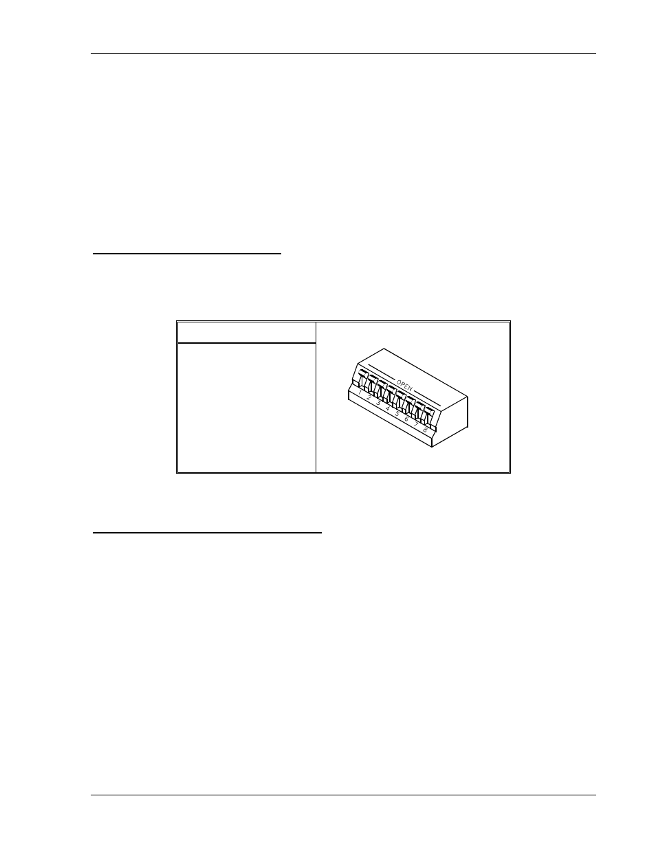
Local Mode Default Configuration
Figure 3–2 shows the default factory settings for switch S1. These controls are used to select
among the various options for programming, sensing, and monitoring. See Section 4.2
Configuring for Remote Programming, Sensing, and Monitoring.
S1 Switch Settings
S1-1 OPEN
S1-2 OPEN
S1-3 OPEN
S1-4 OPEN
S1-5 OPEN
S1-6 OPEN
S1-7 OPEN
S1-8 OPEN
Figure 3–2. Local Mode Default Configuration
Setting Output Voltage and Current Limit
After installing the power supply and connecting the load as described in Section 2 Installation,
set the required output voltage and current limit according to the following front panel
procedure:
1. Turn both the voltage and current controls fully counter–clockwise.
2. Press
the
ENABLE/STANDBY switch to the STANDBY position to disable the power
supply output.
3. Press
the
LOCAL/REMOTE switch to the LOCAL position for front panel operation.
4. Turn
the
POWER switch ON.
5. Press and hold the V&I PREVIEW button to display the voltage and current control
settings on the voltmeter and ammeter displays.
M362000-01 Rev E
3-3