AMETEK HPD Series GPIB-Multichannel User Manual
Page 45
Installation and Configuration
User Lines
41
User Lines
Connection
(XT, HPD,
XPD)
Figure 2.11 User Signals Connector (XT, HPD and XPD)
Use a standard 8-connector RJ45 connector and data cable to connect to the user
lines.
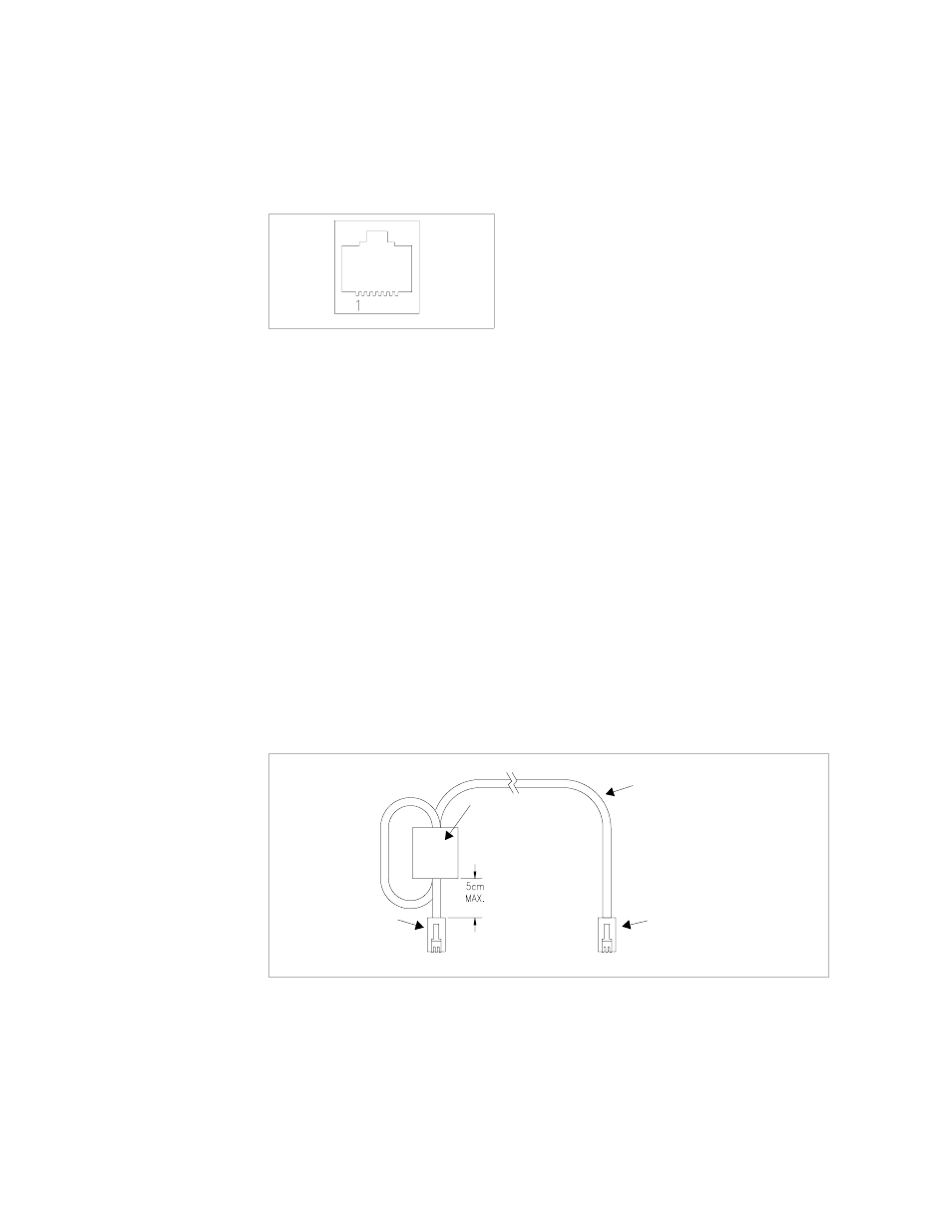
Add a ferrite block to reduce radiated emission. The one inch square ferrite block
with built-in housing clip is packaged and shipped with the power supply interface
card.
To install the ferrite block:
1. Position the block no more than 5 cm (2 in.) from the power supply end of the
user cable.
2. Open the ferrite block housing.
3. Loop the cable through the ferrite block. See
Figure 2.12, “XT, HPD, XPD User
Cable with Ferrite Block” on page 41
.
4. Close the housing clip.
The ferrite block ensures that the power supply system meets radiated emission
requirements for CE mark.
Figure 2.12XT, HPD, XPD User Cable with Ferrite Block
J7 User Cable
Ferrite Block
To User Custom Interface
To J7 Connector