Mechanical construction, Be ck ho ff – BECKHOFF BK7300 User Manual
Page 12
Basic information
8
BK7300
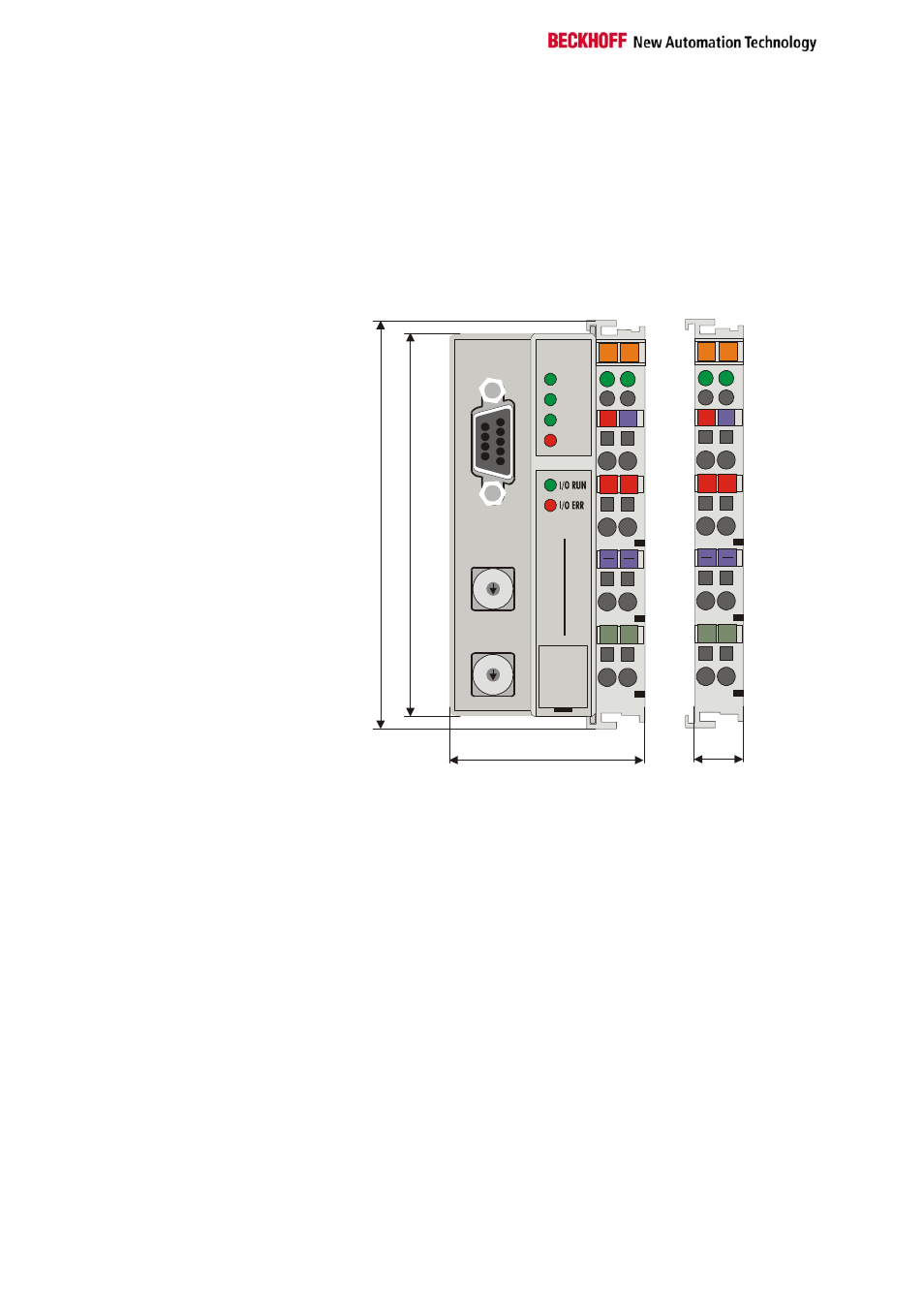
Mechanical construction
The Beckhoff bus terminal system is remarkable for its compact
construction and high degree of modularity. When you design the
installation you will need to plan for one bus coupler and some number of
bus terminals. The dimensions of the bus couplers do not depend on the
fieldbus system. If you use large plugs, for example like some of the bus
plugs used for the PROFIBUS, they may protrude above the overall height
of the cabinet.
Dimensions of a bus
coupler
02
02
01
01
+
+
+
+
PE
PE
PE
PE
RUN
RX
TX
MODBUS
BE
CK
HO
FF
24V
24V
0V
0V
0
9
8
7
6
5 4
3
2
1
0
9
8
7
6
5 4
3
2
1
BK 7300
100
94
47
12
Error
The overall width of the construction is the width of the bus coupler,
including the bus end terminal, plus the width of the installed bus terminals.
The bus terminals are 12 mm or 24 mm wide, depending on their function.
Depending on the gauge of cables used the overall height of 68 mm may
be overstepped by about 5 mm to 10 mm by the cables at the front.
Assembly and connections
It takes only a slight pressure to latch the bus coupler and the various bus
terminals onto a supporting 35 mm rail and a locking mechanism then
prevents the individual housings from being removed. You can remove
them without effort if you first release the latching mechanism by pulling the
orange tab. You should carry out work on the bus terminals and the bus
coupler only while they are switched off: if you plug or unplug components
while the power is on you may briefly provoke some undefined state (and,
for instance, reset the bus coupler).
Maximum number of
terminals
You can attach up to 64 bus terminals in series on the right-hand side of
the bus coupler. When you assemble the components, make sure that you
mount the housings so that each slot comes together with the
corresponding key. You cannot make any functional connections merely by
pushing the housings together along the supporting track. When they are
correctly mounted there should be no appreciable gap between the
adjacent housings.