Bk7300, 5 v 5: gnd 3: rxd/txd 8: rxd/txd – BECKHOFF BK7300 User Manual
Page 20
MODBUS
16
BK7300
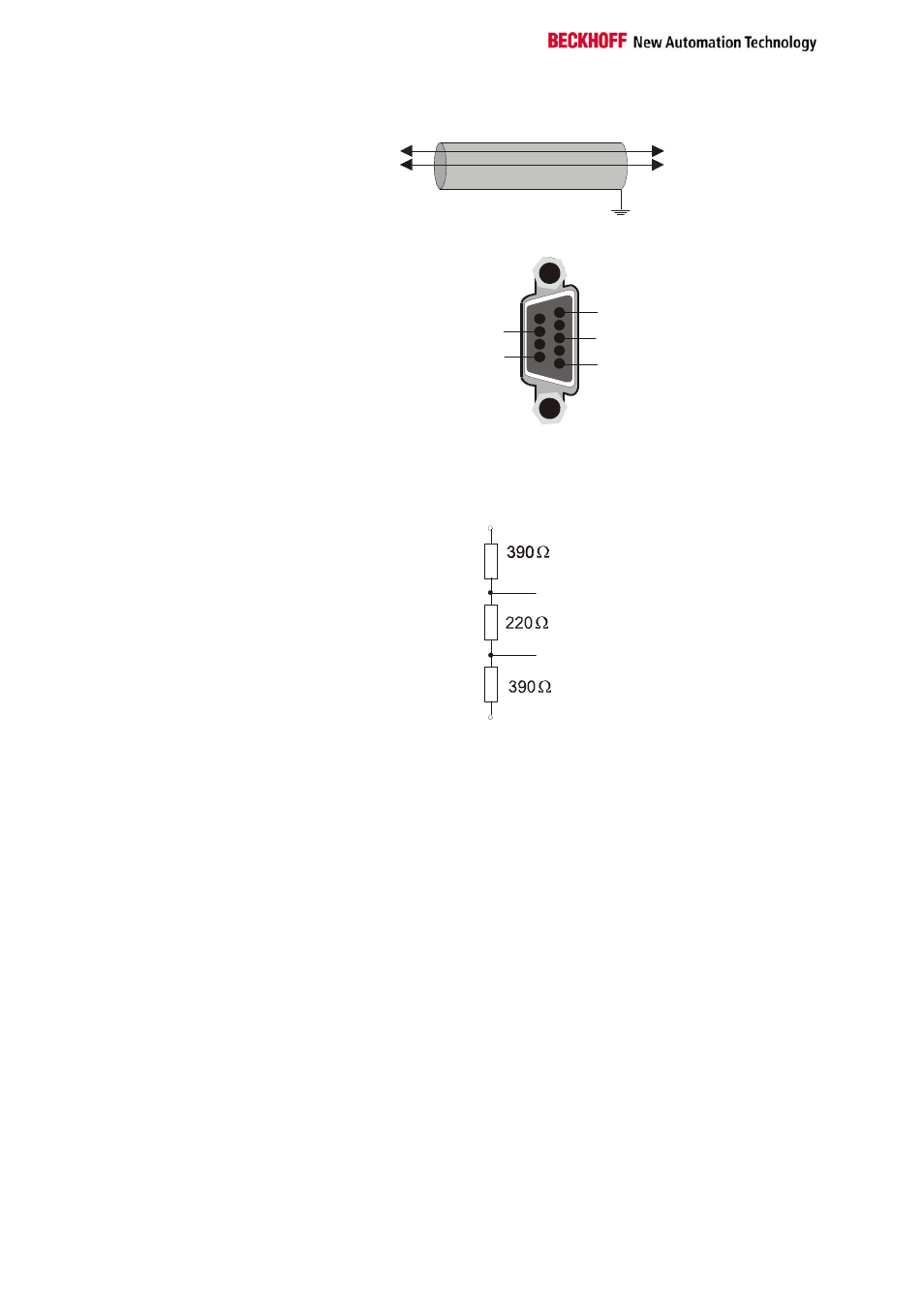
Cable
BK7300
TxD/RxD (3)
RxD/TxD (8)
BK7300
RxD/TxD (3)
TxD/RxD (8)
shield
PE
Sub-D socket
1
6: 5 V
5: GND
3: RxD/TxD
8: RxD/TxD
Bus termination
The MODBUS requires termination resistors at the beginning and end of
the bus lines.
RxD/TxD (3)
TxD/RxD (8)
GND (5)
5 V (6)
Process Data and Memory Map
The following example illustrates how the process image is constructed in
the coupler, and the functions of the MODBUS telegram with which digital
and analogue values can be read.
The input process image in the BK7300 starts from address 0x0000. All the
byte-oriented bus terminals (see Appendix) are entered here into the
process image first. The bit-oriented bus terminals them follow, and each
word is filled before starting a new one.
The output process image starts at address 0x0800. The byte-oriented bus
terminals are again here entered first, and the bit-oriented terminals follow.
All the digital signals can be directly addressed with functions 1, 2, 5 and
15.