Read analogue inputs (function 4) – BECKHOFF BK7300 User Manual
Page 27
MODBUS
BK7300
23
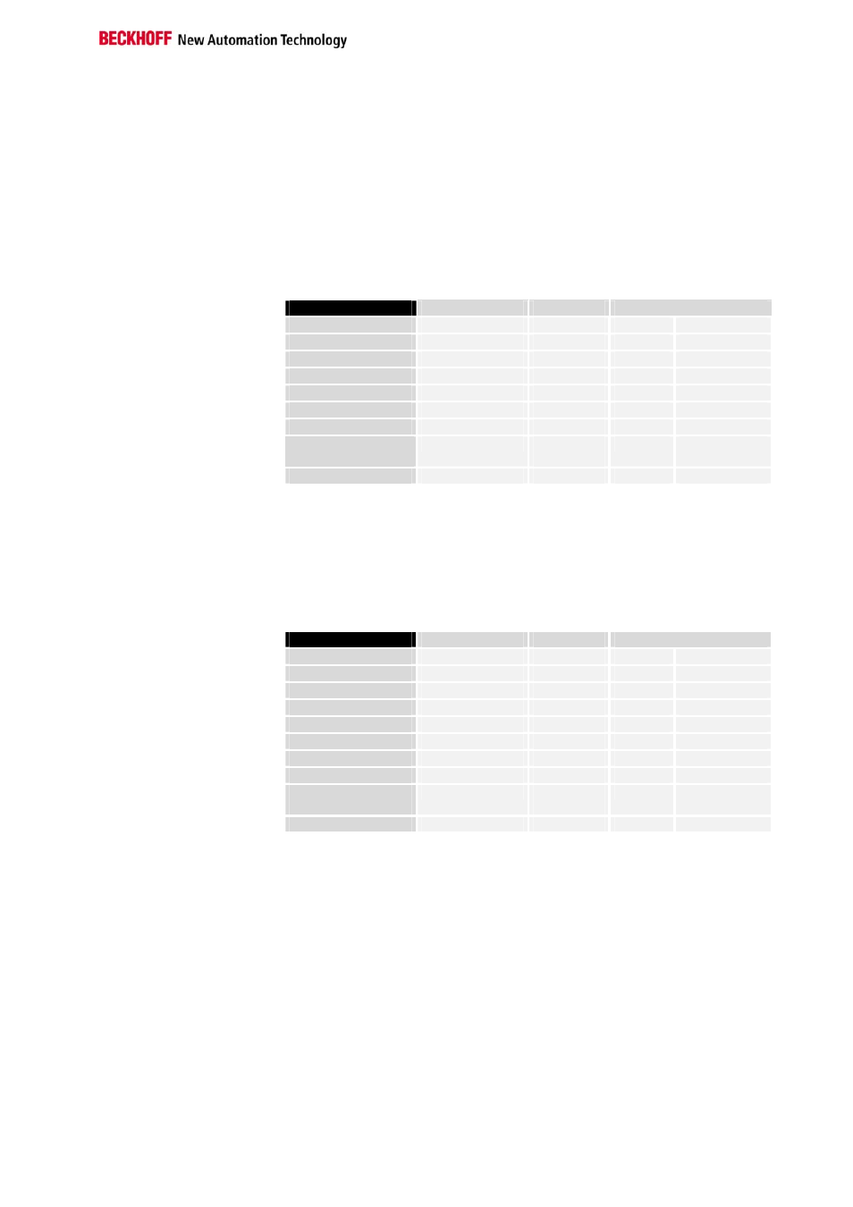
Read Analogue Inputs (Function 4)
READ INPUT REGISTER
Function 4 is used to read the analogue inputs.
In this example the first two analogue inputs of slave number 11 are read.
The analogue outputs begin at offset 0x0000 (hex). The length indicates
the number of words to be read. A KL3002 has 2 words of input data,
which is why the value to be entered in "Count low" is two.
Query
Byte Name
Example
RTU
ASCII
Start frame
„:“
0x3A
Slave address 11
0x0B
„0B“
0x30, 0x42
Function code 4
0x04
„04“
0x30, 0x34
Start address high 0
0x00
„00“
0x30, 0x30
Start address low 0
0x00
„00“
0x30, 0x30
Count high 0
0x00
„00“
0x30, 0x30
Count low 2
0x02
„02“
0x30, 0x32
Error Check
LRC / CRC
0x71
0x61
„EF“
0x45, 0x46
End of frame
t1-t2-t3
CRLF
0xD, 0xA
Response
The coupler answers with byte count 4, i.e. 4 bytes of data are returned.
The request was for 2 analogue channels, and these will now be
distributed over 2 words. In the analogue input process image, the first
channel has the value 0x0038, while the second channel has the value
0x3F1B.
Byte Name
Example
RTU
ASCII
Start frame
„:“
0x3A
Slave address 11
0x0B
„0B“
0x30, 0x42
Function code 4
0x04
„04“
0x30, 0x34
Count byte 4
0x04
„04“
0x30, 0x30
Data 1 high byte 0
0x00
„00“
0x30, 0x30
Data 1 low byte 56
0x38
„38“
0x33, 0x38
Data 2 high byte 63
0x3F
„3F“
0x33, 0x46
Data 2 low byte 11
0x0B
„0B“
0x30, 0x42
Error Check
LRC / CRC
0x80
0x7E
„6A“
0x36, 0x41
End of frame
t1-t2-t3
CRLF
0xD, 0xA