Settings and parameterization, Be ckh of f – BECKHOFF BK7300 User Manual
Page 21
MODBUS
BK7300
17
02
+ +
PE
PE
PE
PE
RUN
RX
TX
MODBUS
BE
CKH
OF
F
24V
0V
0
9
8
7
6 5 4
3
2
1
0
9
8
7
6
5 4
3
2
1
BK
7300
+ +
PE PE
+ +
PE PE
PE PE
+
PE
+
PE
+ +
PE PE
Error
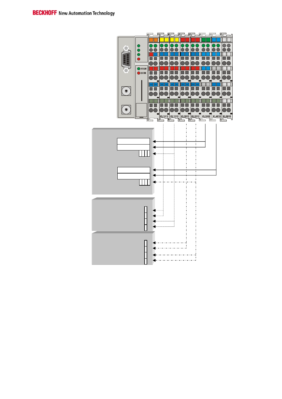
Settings and Parameterization
The Modbus is parameterized by means of the rotary switch on the
BK7300. Only the bus coupler's end terminal may be inserted for this.
Only plug the KL9010 into the BK7300. Use the rotary switch to select the
parameters. The x10 address switch is used to select the parameter, while
the x1 address switch is used for the associated setting. The settings can
be found in the table. Connect the bus coupler's 24 V supply, and the
Modbus coupler will now start up in parameterization mode. The LEDs WD,
RX, TX and ERROR are now toggled, and the LEDs I/O RUN and I/O ERR
give the function value.
Input Function 4,23
0x0000
0x0001
0x0002
Output Function 3,6,16,23
0x0800
0x0801
0x0802
Input Function 2
0x0001
0x0002
0x0003
0x0004
WORD 1
WORD 2
WORD 1
WORD 2
Output Function 1,5,15
0x0001
0x0002
0x0003
0x0004