Read digital inputs (function 2) – BECKHOFF BK7300 User Manual
Page 25
MODBUS
BK7300
21
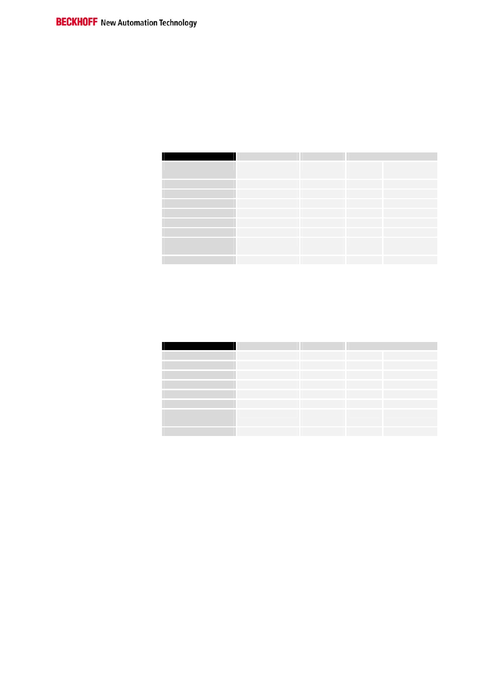
Read Digital Inputs (Function 2)
READ INPUT STATUS
Function 2 can be used to read the digital input data.
In this example the first 10 digital inputs of slave number 11 are read. The
start address is zero. If an offset is to be entered, this is done in the "Start
address" field.
Query
Byte Name
Example
RTU
ASCII
Start frame
„:“
0x3A
Slave address 11
0x0B
„0B“
0x30, 0x42
Function code 2
0x02
„02“
0x30, 0x32
Start address high 0
0x00
„00“
0x30, 0x30
Start address low 0
0x00
„00“
0x30, 0x30
Count high 0
0x00
„00“
0x30, 0x30
Count low 10
0x0A
„10“
0x31, 0x30
Error Check
LRC / CRC
0xF8
0xA7
„E3“
0x45, 0x33
End of frame
t1-t2-t3
CRLF
0xD, 0xA
Response
The coupler answers with byte count 2, i.e. 2 bytes of data are returned.
The request was for 10 bits, and these are now distributed over 2 bytes.
The first bit in the input process image of the BK7300 is set, and the
coupler returns a "1" in the first data byte.
Byte Name
Example
RTU
ASCII
Start frame
„:“
0x3A
Slave address 11
0x0B
„0B“
0x30, 0x42
Function code 2
0x02
„02“
0x30, 0x32
Byte Count 2
0x02
„02“
0x30, 0x32
Data 0..7 1
0x01
„01“
0x30, 0x31
Data 8..15 0
0x00
„00“
0x30, 0x30
Error Check
LRC / CRC
0x20
0x29
„F0“
0x46, 0x30
End of frame
t1-t2-t3
CRLF
0xD, 0xA