2 input channel 7911 - rear panel, Input channel 7911 - rear panel -9 – Cadac C-Type User Manual
Page 23
Advertising
Input channel module 7911
2-9
Revision C2005-2
C-Type
515
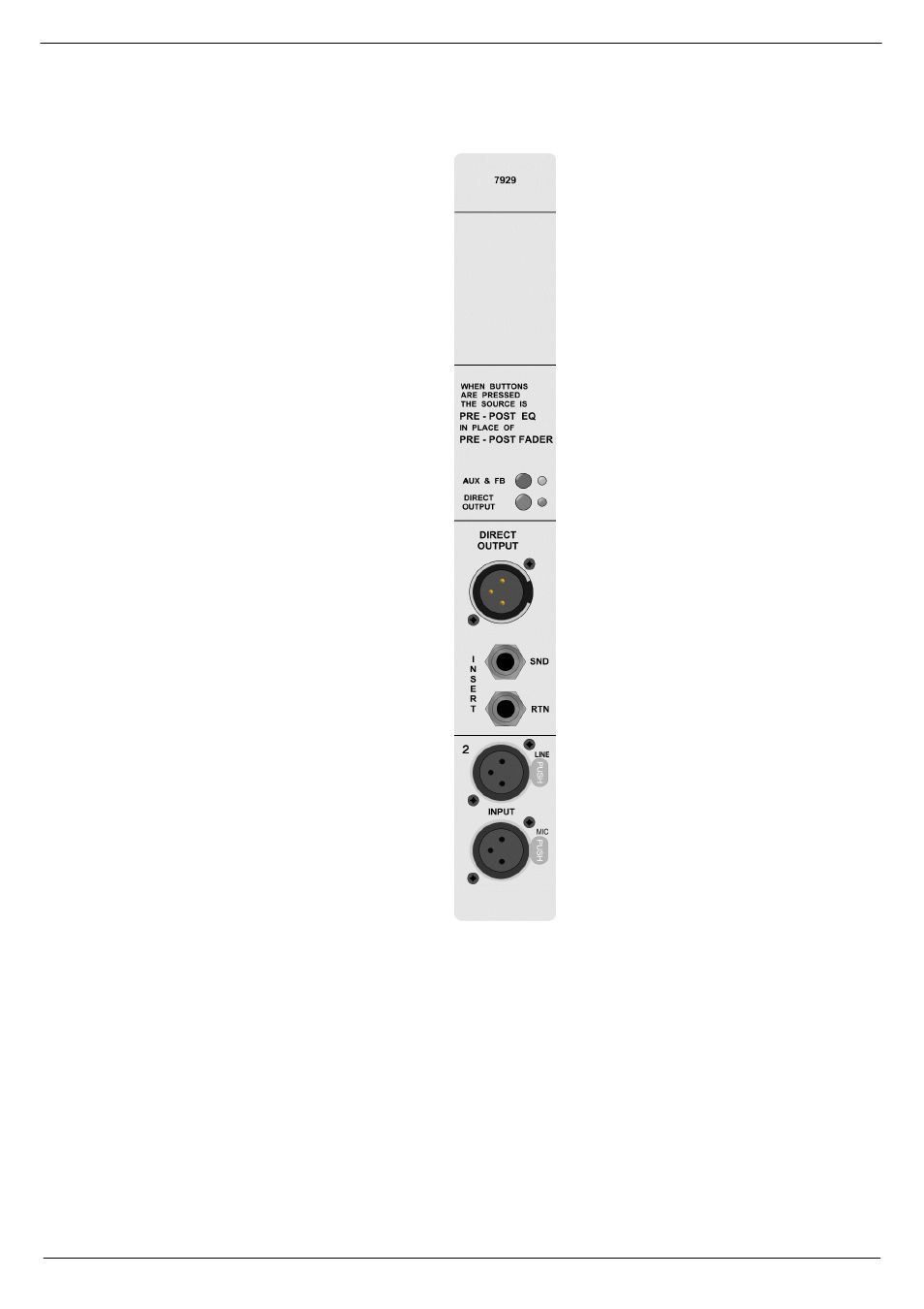
,QSXW#&KDQQHO#:<44#0#UHDU#SDQHO
AUX AND FOLDBACK SWITCH
DIRECT OUTPUT SWITCH
DIRECT OUTPUT
SEND
RETURN
LINE INPUT
MICROPHONE INPUT
Inputs and Outputs are electronically bal-
anced and connected via 3-pin XLRs and
follow the wiring convention:
PIN 1 = Screen
PIN 2 = In-phase signal (hot)
PIN 3 = Out-of-phase signal (cold)
The 0.25” TRS jack connectors use the
wiring convention:
TIP = In-phase signal (hot)
RING = Out-of-phase signal (cold)
SLEEVE = Screen
IMPORTANT NOTE: Pin 1 on XLR con-
nectors and the ‘sleeve’ connections
on the jack sockets are connected to
the FRAME. This is to ensure that the
console can comply with the Electric
Compatibility (EMC) directive.
Advertising