2 osc, png & comms module - rear panel, Osc, png & comms module - rear panel -8 – Cadac C-Type User Manual
Page 58
7-8
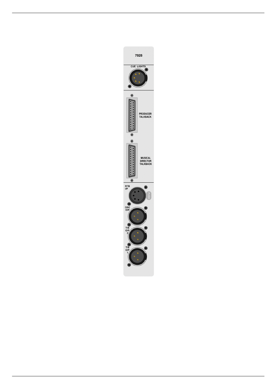
OSC, PNG & Communications Module 7913
C-Type
Revision C2005-2
:15
26&/#31*#)#&RPPV#0RGXOH#0#UHDU#SDQHO
Switched output for the CUE LIGHTS
provide +12VDC at a maximum current
of 100mA (internally fused). This output
is intended for use with standard triac
controlled mains cue light.
The producers talkback control box
(option) is connected via this 25-way D-
type connector (for connection details,
see chapter 8).
The Music Director’s talkback control box
(option) is connected via this 25-way D-
type connector (for connection details,
see chapter 8).
Microphone level input for Reverse Talk-
back 2. With switch contact for control
lines.
Output from the internal sine wave oscil-
lator/Pink Noise Generator.
TB O/P1 & O/P2 are balanced line level
outputs from the desk talkback system.
IMPORTANT NOTE: Pin 1 on XLR con-
nectors and the ‘sleeve’ connections
on the jack sockets are connected to
the FRAME. This is to ensure that the
console can comply with the Electric
Compatibility (EMC) directive.
The wiring convention for the cue lights
output is:
PIN1 = GROUND
PIN2 = LINK OR SWITCH
CONTACTS
PIN3 = LINK OR SWITCH
CONTACTS
PIN4 = GREEN LAMP
PIN5 = RED LAMP
The wiring convention for the RTB I/P is:
PIN1 = SCREEN
PIN2 = + PHASE
PIN3 = – PHASE
PIN4 = LINK OR SWITCH
CONTACTS
PIN5= LINK OR SWITCH CONTACTS
Outputs for OSC, T/B O/P2 and
T/B O/P1 are electronically bal-
anced and connected via 3-pin
XLRs and follow the wiring
convention:
PIN 1 = Screen
PIN 2 = In-phase signal (hot)
PIN 3 = Out-of-phase signal
(cold)