Fundamentals 19, Central assignment module, Fundamentals – Cadac CDC four User Manual
Page 19
Revision 1 2012-13
CDC FOUR
19
Fundamentals
Although the CDC FOUR control surface and operating system has been
designed to retain the familiarity and facilities of an analogue console, there are a
number of important aspects of its operation which differ markedly from analogue
mixers. These include the following concepts:
• Assignability - a single channel strip whose controls can be assigned to any
of the internal signal channels;
• Layers – the faders can be switched to control another set of channels or
groups, resulting in a small control surface for a large configuration mixer;
• TFT screen – most of the mixer’s controls and statuses are accessible
through the built-in display as well as by using hardware controls; some mixer
functions are only available via the screen;
• Soft keys – various controls whose functions vary depending on the current
state of the display, or of other mixer settings.
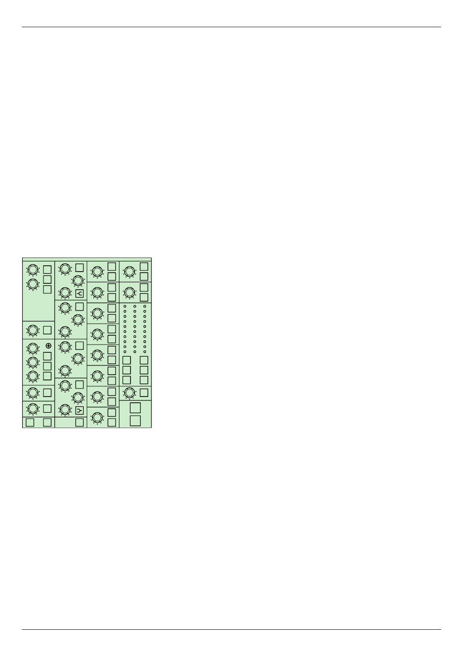
Central Assignment Module
The Central Assignment Module (CAM) is essentially a single,
fully-featured channel strip, such as would be found on an
analogue mixer. The obvious differences are that potentiometers
are replaced by continuous (360°) rotary encoders, and the push-
buttons are electronically latching and internally illuminated. The
encoders have a “press” function; turning the encoder knob while
pressing it in allows a finer degree of parameter adjustment. The
use of rotary encoders means that the value of the parameter
which the control varies is not related to the physical position
of the knob – in fact, the knobs do not have a pointer of any
kind. Another implication of this system is that all the channel
parameters have default values which have nothing to do with
knob positions; these values can be regarded collectively as the
“initial state” of the channel. The actual value of each parameter
is available from the TFT display; this topic is covered in greater
detail under “Screen displays”, see page 25.
The CAM controls the mixer’s DSP section, and is used to set the
channel parameters for the following mixer sections:
• All mono mic/line channels
• Stereo inputs 1-8
• Subgroups 1-4
• Aux. sends 1-8
• FX returns 1 and 2Note that unlike an analogue mixer, many of the channel
facilities found on an input channel strip are available to the output sections
of the CDC FOUR. Furthermore, there is no significant difference in the
facilities available to stereo line input channels compared to mono mic/line
input channels.
However, it should be noted that not every channel facility is available to all types
of signal channel. The exceptions are noted in a later section of the manual, see
“Audio channel descriptions” on page 31.
S
mS
+
-
+
-
L
R
+
-
+
-
0
3
6
9
12
15
18
21
GT
LIM
L
R
GR
+
-
+
-
20:1
1:1
+
-
HI
LO
W
N
+
-
HI
LO
W
N
+
-
HI
LO
W
N
+
-
HI
LO
W
N
LIM
THR
DLY
COMP
GATE
LVL
RAT
THR
THR
TRIM
HPF
FREQ
Q
FREQ
FREQ
FREQ
Q
Q
Q
PAN
AUX 1
AUX 2
AUX 3
AUX 4
AUX 5
AUX 6
AUX 7
AUX 8
FX 1
FX 2
HMF
HF
LMF
LF
dB
CENTRAL ASSIGNMENT MODULE
0
3
6
9
12
15
18
24
36
54
48V
REV
HPF
IN
IN
AUT
VIN
IN
IN
BYP
PST
IN
1
2
3
L
R
4
IN
ON
PRE
ON
PRE
ON
PRE
ON
PRE
EQ
IN
SOLO
MUTE
IN
IN
IN
ON
PRE
ON
PRE
ON
PRE
ON
PRE
ON
PRE
ON
PRE
dB
dB
dB
∞
0
0
0
0
0
0
0
0
0
0
∞
∞
∞
∞
∞
∞
∞
∞
∞