Cadac CDC four User Manual
Page 36
36
Revision 1 2012-13
CDC FOUR
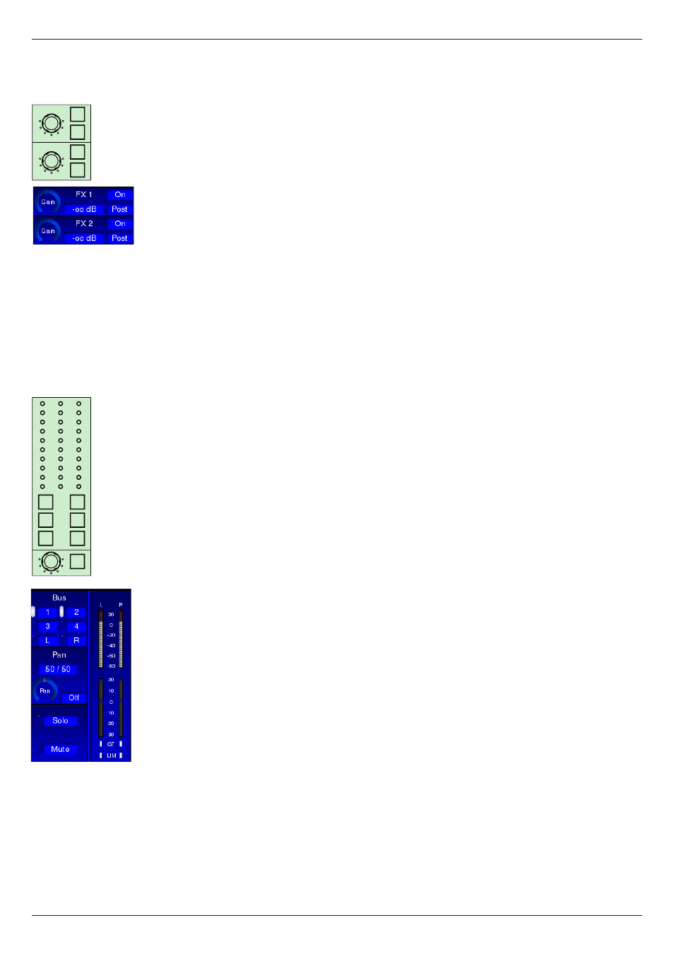
FX Sends:
The CDC FOUR has two internal DSP-based effects processors, which provide
a selection of time-domain effects such as delay and reverb. The inputs to these
are additional sends, denoted FX1 and FX2, and the outputs are routed to the
main LR stereo buss or Groups 1 to 4 via two faders in the OUTPUTS Layer.
See “FX processing” on page 58 for full details.
The two FX sends are identical in operation. For brevity, only FX 1 is described:
FX 1 – level control from the channel to internal FX buss 1. This routes the signal
to FX processor 1. The level control’s range and default settings are the same as
the Aux. sends.
ON – unmutes the feed to FX Send 1. Default is Off.
PRE – default source for FX Send is post-fade, but can be changed to pre-fade
with the PRE button. Both pre- and post-fade sends are post-Channel Mute.
Routing and metering section:
The CDC FOUR has four mono group busses in addition to the main LR stereo
buss. The groups may either be used as subgroups into the main mix or as
additional outputs from the mixer. The usual set of routing buttons and odd/even
panning is provided.
1 - 4 – four buss select buttons which route the channel to Audio Groups 1 to 4
respectively.
L & R – two buss select buttons which route the channel respectively to the L and
R legs of the stereo master buss. Note that the pan control is always in circuit with
respect to the L & R busses.
PAN – allows the channel signal to be panned between odd-numbered busses
(and the L leg of the master buss) and even-numbered busses (and the R leg of
the master buss). Default is “centre” – i.e., equal signal levels are routed to the
selected busses. The adjacent IN button must be enabled for the pan control to
be active for the four groups; it is always operational across the main L/R buss.
IN – enables the PAN control for panning between odd- and even-numbered
groups. Default is Out; in this state, the signal in the channel is sent at equal level
to all busses selected by the routing buttons 1 to 4.
L & R METERS – two 10-segment LED bargraph meters indicating channel
signal level are fitted in the CAM area. With mic/line channels, both L and R
meters give the same indication.
The meters show the pre-fade (and hence pre-
pan) signal level relative to 0 dBFS. The bottom LED is green and illuminates at
-54 dBFS, and thus acts as a “signal present” LED. The top three LEDs are red,
the uppermost indicating the digital peak level of 0 dBFS. The remainder of the
LEDs are yellow.
GR METER – an 8-segment LED bargraph meter indicating the instantaneous
gain reduction being applied by the dynamics section’s compressor.
GT – a red LED which illuminates when the channel’s Noise Gate is opened by
the signal exceeding the threshold.
FX 1
FX 2
ON
PRE
ON
PRE
0
0
∞
∞
L
R
0
3
6
9
12
15
18
21
GT
LIM
L
R
GR
PAN
0
3
6
9
12
15
18
24
36
54
IN
1
2
3
L
R
4