Cata ME 910 User Manual
Page 33
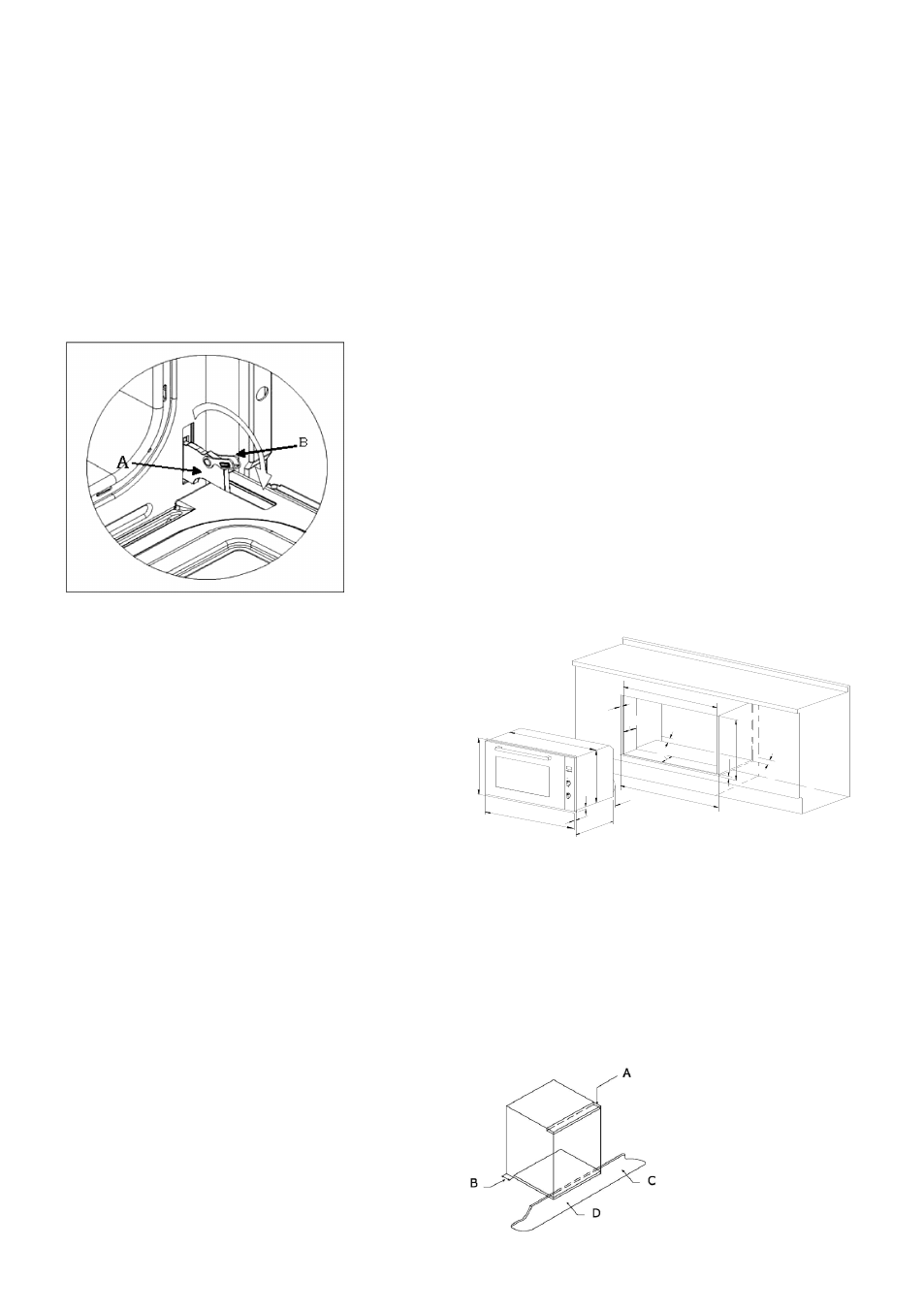
Door type A / B2
The hinges “A” have two moving bolts “B”.
When the bolt “B” is lifted, the hinge comes out of its housing.
Then close the door to the half-way position.
Next, lift the door upwards and remove it, sliding it outwards;
hold the door by the sides close to the hinges when doing this.
To replace the door, first slide the hinges into their grooves
and open the door completely.
Remember to turn the two moving bolts “B” used to engage
the two hinges before closing the door (Fig. 3).
WARNING
• Take care not to remove the hinge locking system when
taking off the door, as the hinge mechanism can spring back
suddenly.
• Never submerge the door in water for any reason.
INSTRUCTIONS FOR INSTALLATION
This appliance must be installed by a competent person, in ac-
cordance with the current version of the UK Safety Rules and
Regulations or their European equivalent:
Urban development regulations (published by the Department
of Environment).
Urban development laws (published by the Scottish Executive
Development Department).
IEE wiring regulations.
Electricity in labour regulations.
PRIOR START-UP OF THE APPLIANCE
When it is unpacked, check that the following parts are with
the oven:
• Instructions and Installation Manual
• oven grid
• 1 tray
• Screws and stoppers for fitting the appliance in the housing
FITTING THE APPLIANCE (see Fig. 5)
These appliances are classified as Class I.
The earth is obligatory as provided for by law. The manufactu-
rer declines all liability in the event that the accident preven-
tion rules have not been followed.
IMPORTANT
The adjacent piece or furniture or cupboard and all the mate-
rials used in the installation must resist a minimum tempera-
ture increase of 85 ºC above the ambient temperature during
use of the appliance.
Certain types of vinyl or laminated kitchen furniture are parti-
cularly susceptible to damage due to decolouration at tempe-
ratures below those indicated.
If the appliance is installed without paying attention to this
temperature limit or if it is placed less than 4 mm from the ad-
jacent cupboards, liability will belong to the owner.
INSTALLATION NOTES
1. The oven has to be installed in a standard gap of 900mm, as
indicated in Fig. 5, whether under a hob or in a column.
2. On inserting the oven in a column, it is essential in order to
ensure there is enough ventilation, to remove the rear panel
of the furniture and have an opening of at least 85-90mm as
indicated in Fig. 5.
3. Check that the oven has been fixed securely in the housing.
Fixing the oven into the cupboard is done using 4 screws “A”
Fig.5. One in each corner of the oven door frame.
Fig. 5: Installation distanced for simple electric ovens of 90
cms wide (the shape of the upper casing may vary) and atta-
chment to the cupboard.
900MIN
480
870MIN
25
6
200MI
N
45min
45min
200
MIN
521
5
478.5
15.5
23.6
897.5
467.6
864.5
Fig. 7: Ventilation and gap requirements for the installation of e
simple electric oven in a standard cooking unit.
Minimum ventilation requirements for upper, base and support
shelves for the rear part of the unit.
A. The support runner must be removed
B. Spacing of 75-90 mm between the wall and the rear part of
the support shelf and the base of the cupboard
C. Base
D. False box front to be assembled