2 ca-0000352 ‘p1’ 19-pin circular connector – Comtech EF Data LPODnet User Manual
Page 25
LPODnet M&C Netbook Accessory
Revision 3
Setup
MN-LPODNET
2–5
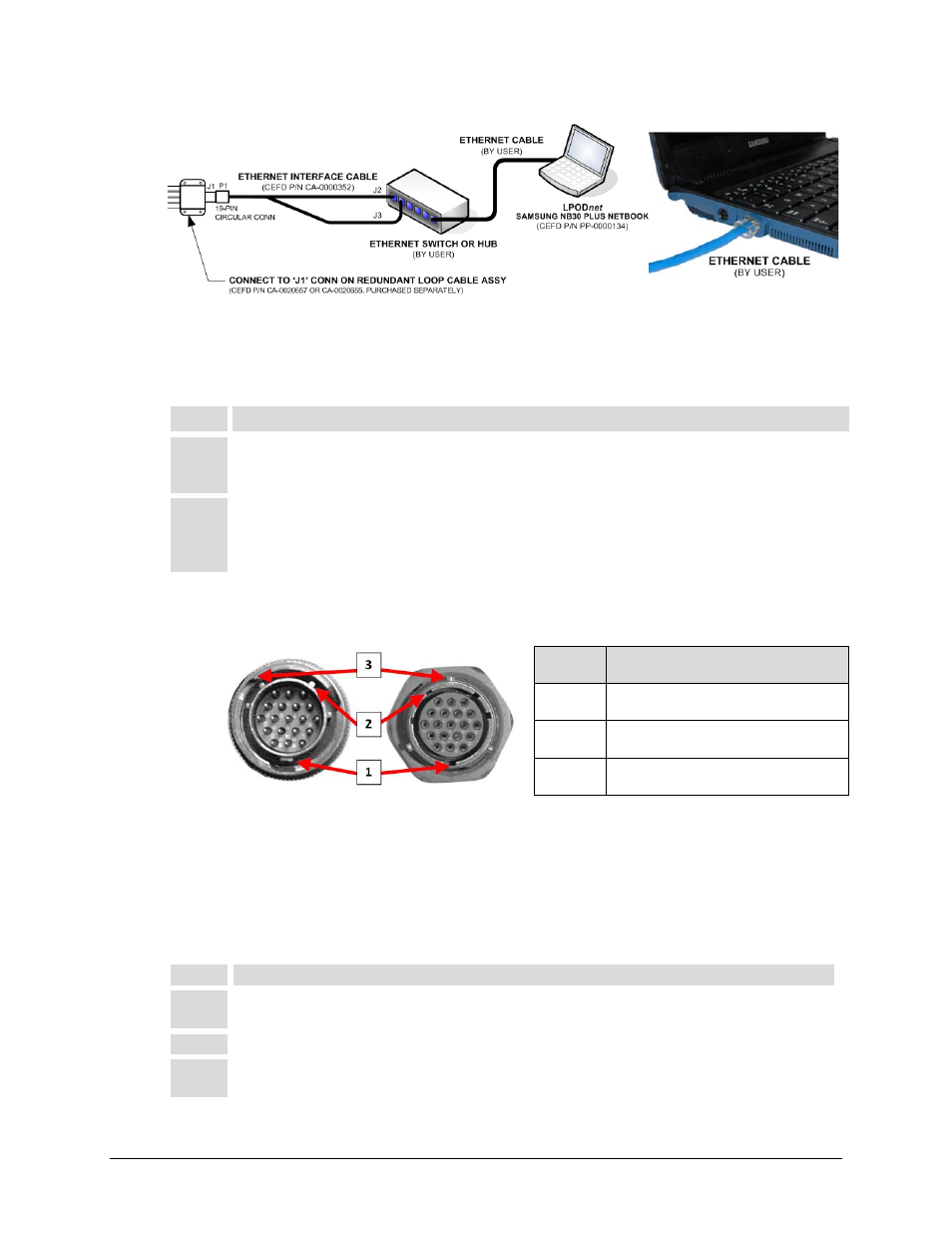
Figure 2-6. CA-0000352 RJ-45 1:1 Redundancy Application Connections
For 1:1 Redundancy applications only – Follow these steps to connect the Ethernet Interface
Cable RJ-45 ‘J2’ and ‘J3’ connectors (Figure 2-6):
Step
Task
1
Typical for each CA-0000352 RJ-45 connection (‘J2’ and ‘J3’): Press down the tab on the pertinent
RJ-45 plug, and then insert the plug into its corresponding jack in the user-provided Ethernet switch or
hub. The connection is complete when the tab ‘clicks’ into position inside the jack.
2
Connect the user-provided Ethernet switch or hub to the LPODnet Netbook with a user-provided Ethernet
cable. Typical for either end of the user cable, press down the tab on the cable RJ-45 plug, and then
insert one plug end into the switch or hub jack, and the other end into the LPODnet’s RJ-45 Ethernet
network jack. The connection is complete when the tab ‘clicks’ into position inside the jack.
2.2.2 CA-0000352 ‘P1’ 19-pin Circular Connector
Feature Description
1
Primary Alignment features
2
Secondary Alignment features
3
Sleeve Lock features
Figure 2-7. CA-0000352 19-pin Circular Connector
The 19-pin circular connector, labeled ‘P1’ on the CA-000352 Ethernet Interface Cable, features
a keyed configuration. Figure 2-7 shows the mating relationship between the ‘P1’ connector and
the ‘J6 | COM1’ socket on the SSPA, or the ‘J1’ socket on the Redundant Loop Cable Assembly
(CEFD P/N CA-0020655 for Rx / Tx applications, or CA-0020657 for Tx-only applications). Follow
these steps to install the CA-0020526 Serial Interface Cable’s male 19-pin circular connector into
the SSPA’s ‘J6 | COM1’ port or the 1:1 Redundant Loop Cable’s ‘J1’ receptacle:
Step
Task
1
Engage the primary and secondary alignment tabs on the male connector with the mating cutouts on
the female socket.
2
Push the male connector into the female socket.
3
Turn the male connector sleeve clockwise until the sleeve lock cutouts engage fully with the female
socket tabs and you hear a “click” sound.