Chapter 2 – DFI CM100-C User Manual
Page 11
www.dfi.com
11
Chapter 2 Hardware Installation
Chapter 2
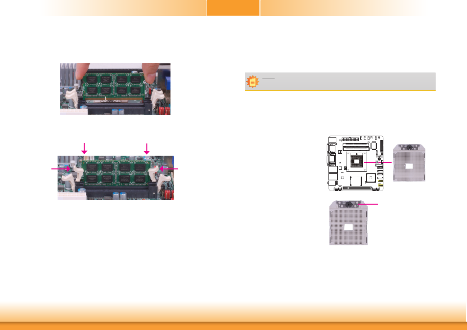
7. Seat the module vertically, pressing it down firmly until it is completely seated in the socket.
The ejector tabs at the ends of the socket will automatically snap into the locked position to
hold the module in place.
6. Grasping the module by its edges, position the module above the socket with the “notch” in
the module aligned with the “key” on the socket. The keying mechanism ensures the
module can be plugged into the socket in only one way.
CPU
Overview
The system board is equipped with a surface mount rPGA 988B CPU socket.
Installing the CPU
1. Make sure the PC and all other peripheral devices connected to it has been powered down.
2. Disconnect all power cords and cables.
3. Locate the FS1r2 (722-pin lidless
micro PGA) socket on the board.
4. Make sure the screw is in its
unlock position. If it’s not, use a
screwdriver to turn the screw to
its unlock position.
Screw in unlocked
position
Note:
The system board used in the following illustrations may not resemble the actual
board. These illustrations are for reference only.