Chapter 2 – DFI CR101-D User Manual
Page 12
www.dfi .com
12
Chapter 2 Hardware Installation
Chapter 2
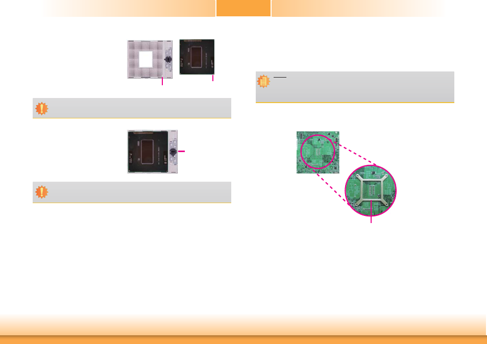
5. Position the CPU above the socket.
The gold triangular mark on the
CPU must align with pin 1 of the
CPU socket.
Pin 1
Gold triangular mark
6. Insert the CPU into the socket until
it is seated in place. The CPU will fit
in only one orientation and can eas-
ily be inserted without exerting any
force. Use a screwdriver to turn the
screw to its lock position.
Screw in
locked position
Important:
Handle the CPU by its edges and avoid touching the pins.
Important:
Do not force the CPU into the socket. Forcing the CPU into the socket may bend the
pins and damage the CPU.
Installing the Fan and Heat Sink
The CPU must be kept cool by using a CPU fan with heat sink. Without sufficient air circula-
tion across the CPU and heat sink, the CPU will overheat damaging both the CPU and system
board.
1. On the solder side of the board, match the retention module base to the mounting holes
around the CPU socket.
Retention module base
2. Turn to the component side of the board making sure the retention module base is posi-
tioned and fitted properly under the board.
3. Apply a thin layer of thermal paste on top of the CPU. Do not spread the paste all over
the surface. When you later place the heat sink on top, the compound will disperse
evenly.
Note:
• Use only certified fan and heat sink.
• Your fan and heat sink package usually contains the fan and heat sink assembly,
and an installation guide. If the installation procedure in the installation guide dif-
fers from the one in this section, please follow the installation guide in the package.