Chapter 2 – DFI HD632-H81 User Manual
Page 16
www.dfi .com
16
Chapter 2 Hardware Installation
Chapter 2
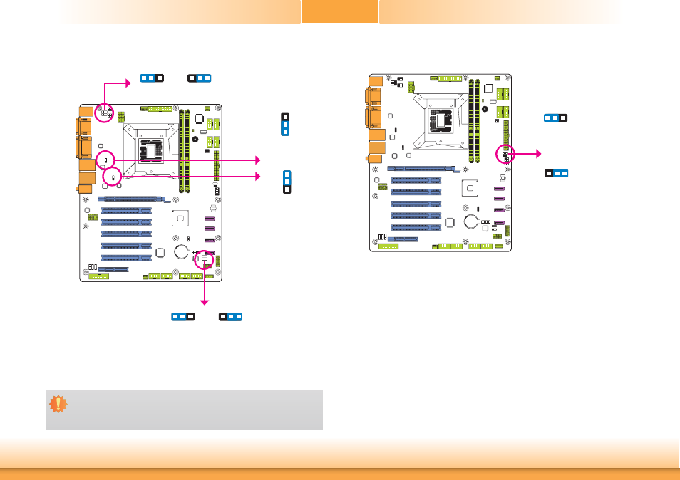
JP4, JP5, JP6 and JP8 are used to select the power of the USB devices. Selecting +5V_standby
will allow you to use a USB device to wake up the system.
USB Power Select
Important:
If you are using the Wake-On-USB Keyboard/Mouse function for 2 USB ports, the
+5V_standby power source of your power supply must support ≥1.5A. For 3 or more
USB ports, the +5V_standby power source of your power supply must support ≥2A.
Power-on Select
JP10
1-2 On:
Power-on via power button
(default)
2-3 On:
Power-on via AC power;
Power-on via WOL after G3
USB 8-9
(JP4)
USB 2-3
(JP8)
2-3 On:
+5V_standby
1-2 On: +5V
(default)
3
1 2
3
1 2
USB 4-5
(JP6)
USB 0-1
(JP5)
1
3
2
1
3
2
2-3 On:
+5V_standby
1-2 On: +5V
(default)
2-3 On:
+5V_standby
1-2 On: +5V
(default)
3
1 2
3
1 2
3
1 2
3
1 2
JP10 is used to select the method of powering on the system. If you want to use the power
button, set pins 1 and 2 to On.
To power-on via WOL after G3:
1. Set JP10 pins 2 and 3 to On.
2. Set the “After G3” field to Power Off/WOL.
3. Set the “GbE Wake Up From S5” to Enabled.
To power-on via AC Power:
1. Set JP10 pins 2 and 3 to On.
2. Set the “After G3” field to Power On.