Chapter 2, Chassis intrusion connector, Power connectors – DFI HD632-H81 User Manual
Page 26
www.dfi .com
26
Chapter 2 Hardware Installation
Chapter 2
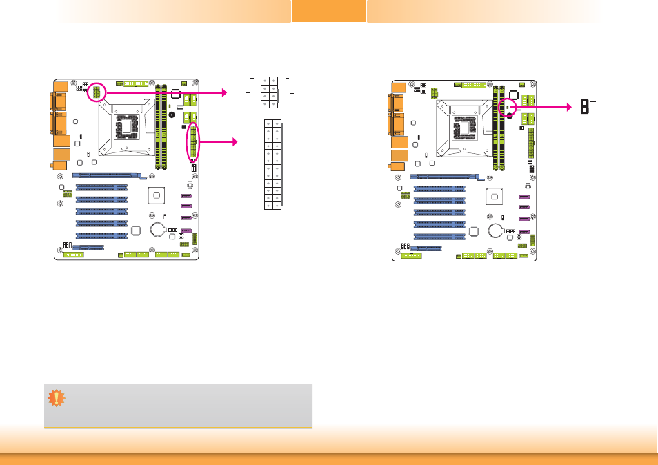
Chassis Intrusion Connector
The board supports the chassis intrusion detection function. Connect the chassis intrusion
sensor cable from the chassis to this connector. When the system’s power is on and a chassis
intrusion occurred, an alarm will sound. When the system’s power is off and a chassis intrusion
occurred, the alarm will sound only when the system restarts.
1
2
Ground
Signal
Chassis
Intrusion
Power Connectors
Use a power supply that complies with the ATX12V Power Supply Design Guide Version 1.1.
An ATX12V power supply unit has a standard 24-pin ATX main power connector that must be
inserted into the 24-pin connector. The 8-pin +12V power connector enables the delivery of
more +12VDC current to the processor’s Voltage Regulator Module (VRM).
The power connectors from the power supply unit are designed to fit the 24-pin and 8-pin
connectors in only one orientation. Make sure to find the proper orientation before plugging
the connectors.
The system board requires a minimum of 300 Watt power supply to operate. Your system
configuration (CPU power, amount of memory, add-in cards, peripherals, etc.) may exceed the
minimum power requirement. To ensure that adequate power is provided, we strongly recom-
mend that you use a minimum of 400 Watt (or greater) power supply.
Important:
Insufficient power supplied to the system may result in instability or the add-in boards
and peripherals not functioning properly. Calculating the system’s approximate power
usage is important to ensure that the power supply meets the system’s consumption
requirements.
ATX
power
+12V
Power
+12V
Ground
1
4
5
8
13
12 24
1
+3.3VDC
+3.3VDC
COM
+5VDC
COM
+5VDC
COM
PWR_OK
+5VSB
+12VDC
+12VDC
+3.3VDC
+3.3VDC
-12VDC
COM
PS_ON#
COM
COM
COM
NC
+5VDC
+5VDC
+5VDC
COM