Chapter 2 – DFI HD632-H81 User Manual
Page 29
www.dfi .com
29
Chapter 2 Hardware Installation
Chapter 2
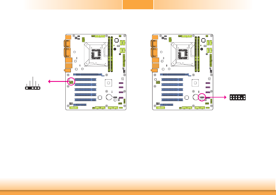
LPC Connector
The Low Pin Count Interface was defined by Intel
®
Corporation to facilitate the industry’s
transition towards legacy free systems. It allows the integration of low-bandwidth legacy I/O
components within the system, which are typically provided by a Super I/O controller. Fur-
thermore, it can be used to interface firmware hubs, and embedded controller solutions. Data
transfer on the LPC bus is implemented over a 4 bit serialized data interface, which uses a
33MHz LPC bus clock. For more information about LPC bus refer to the Intel
®
Low Pin Count
Interface Specification Revision 1.1’.
S/PDIF Connector
The S/PDIF connector is used to connect an external S/PDIF port. Your S/PDIF port may be
mounted on a card-edge bracket. Install the card-edge bracket to an available slot at the rear
of the system chassis then connect the audio cable to the S/PDIF connector. Make sure pin 1
of the audio cable is aligned with pin 1 of the S/PDIF connector.
1
5
+5V
Key
SPDIF out
Ground
SPDIF in
S/PDIF
LPC
Debug
2
1
12
11