DR Power VT1 (1-ton) (Feb 2012 - Present) User Manual
Page 11
CONTACT US AT
www.DRpower.com 11
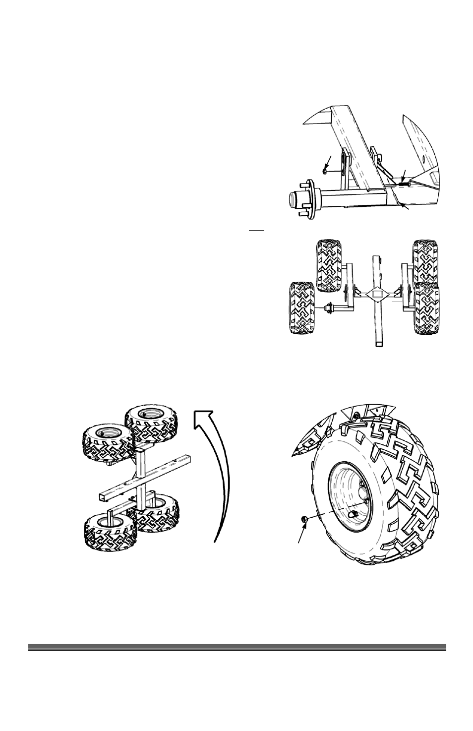
3. Insert a M8 x 30mm Mounting Bolt (Figure 7) from the inside of the
Frame and through the Tab on the Axle Pivot Pin. Install a M8 Flange Nut
and tighten with a 12mm Socket, holding the Bolt with a 13mm Wrench.
4. Insert a Cotter Pin (Figure 7) through the Left and Right Axle Pivot Pins
and bend the legs over with Pliers.
5. Install the Left and Right wheels on the Axles with the supplied Lug Nuts
until snug with a 21mm Socket and 5" Extension; they will be torqued
later.
NOTE: The Wheels are marked L (Left) and R (Right), as they are directional
Tires. Since the Main Frame is upside down, the Left Wheels should be
installed on the Right Side and the Right Wheels on the Left Side (Figure
8). Make sure the Valve Stem(s) face outwards. The Lug Nuts must be
installed with the tapered side of the Nuts facing the Hub of the Wheel
(Figure 9).
6. Turn the unit over with the assistance of at least one other person.
NOTE:
The easiest way of turning the unit over is to lift the two Wheels on the
Right Side of the Trailer while pivoting over the Wheels on the Left Side
(Figure 10).
M8 x 30mm
Bolt
M8 Nut
Figure 7
Cotter Pin
Right
Left
Figure 8
Front
Figure 9
Tapered side
facing in
Figure 10