DR Power VT1 (1-ton) (Feb 2012 - Present) User Manual
Page 15
CONTACT US AT
www.DRpower.com 15
Attaching the Crane
Tools Needed:
x
22mm and 17mm Wrench
x
21mm, 16mm and 30mm Sockets
x
Large Adjustable Wrench
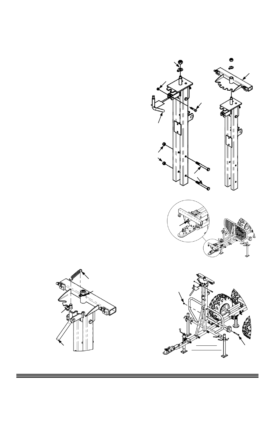
1. Remove the Lock Nut, Flat Washer, and Tabbed Washer from the
top of the Crane (Figure 24) along with the Pivot Lock Handle by
removing the M10 x 1.75mm Bolt and M10 Lock Nut with a 16mm
Socket for the Bolt and a 17mm Wrench for the Nut.
2. Remove the two M14 x 140mm Bolts and M14 Nuts from the
Crane with a 21mm Socket for the Bolt and a 22mm Wrench for
the Nut.
3. Install the Boom Pivot (Figure 25) on top of the Crane with the
Mounting Boss pointing up and re-install the Tabbed Washer 1
st
,
Flat Washer 2
nd
, then the Lock Nut. Do not tighten yet.
4. Lay the Crane on the Operator Guard, with the Diagonal Support
of the Operator Guard between the two legs of the Crane (Figure
26). Snug the Lock Nut on the Boom Pivot using a large
Adjustable Wrench, or a 30mm Socket making sure the Tabbed
Washer is facing downward. Back the Nut off ½ turn, to make
sure the Boom Pivot rotates freely.
5. With the assistance of another person, rotate and lift the Crane to the
vertical position (Figure 27). Install two M14 x 140mm Bolts, from the Left
side, through the Crane and Operator Guard and attach the M14 Lock
Nuts. Tighten using a 21mm Socket on the Bolt and a 22mm Wrench on
the Nut (Figure 27).
6. Install the Pivot Lock Handle in the orientation shown in Figure 27 with the
hardware removed in Step 1 of this section.
7. Install the Extension Spring on the Boom Pivot Handle. Hook one end
around the Handle and the other end through the Tabbed Washer (Figure
28) on the Boom Pivot. Ensure that the Spring is properly seated in the
Groove on the Boom Pivot Handle.
Figure 24
Pivot Lock
Handle
Lock Nut, Flat
Washer and
Tabbed Washer
M10 Bolt
M10 Lock Nut
M14 Bolt
M14 Nut
Figure 25
Boom Pivot
Figure 26
Lock
Nut
Figure 28
Extension Spring
Boom Pivot
Handle
Tabbed Washer
Groove
Figure 27
M14 x 140mm
Bolt(s)
M14 Lock
Nut(s)
Mesh Guard
Hidden for Clarity