ELICA STENAR User Manual
Page 20
20
inside the suction group (1 or 2 fixing points are
necessary for permanent mounting) (Fig. 11).
11. Remove the hood from the lower bracket.
12. Drill at the point marked (Ø8mm) (Fig. 12).
13. Insert 1 or 2 wall screw anchors according to requirement.
14. Apply the flues support bracket „G“ to the wall adherent
to the ceiling, use the flues support bracket as a
perforation diagram (if present, the small slot on the
support must coincide with the line drawn previously on
the wall) and mark two holes with a pencil. Make the
holes (Ø8mm), and insert 2 dowels (Fig. 13).
15. Fix the chimney support bracket to the wall using two
5x45mm screws.
16. Hook the hood onto the bottom bracket.
17. Fix the hood into its final position on the wall
(ABSOLUTELY ESSENTIAL) (Fig. 14).
18. Connect a pipe (pipe and pipe clamps not provided, to be
purchased separately) for discharge of fumes to the
connection ring located over the suction motor unit.
If the hood is to be used in ducting version, the other end
of the pipe must be connected to a device expelling the
fumes to the outside. If the hood is to be used in filter
version, then fix the deflector F to the chimney support
bracket G and connect the other extremity of the pipe to
the connection ring placed on the deflector F (Fig. 13-
15).
19. Connect the electricity.
Attention: only the models illustrated in Fig. 1Q:
Continue from the installation sequence number 23.
20. Apply the chimney stacks and fasten them at the top to
the chimney support „G“ (20b) using 2 screws (20a)
(Fig. 16).
Only for model with optical fibers point lighting (Fig.
1G):
Check that the chimneys may be removed to permit
access to the optical fibers lamp housing area.
Only for the model with control panel on chimney
flue (Fig. 1L- 17):
Insert the command plate from the motor group through
the chimney flue slit from the inside towards the outside
(20c).
Carry out the connection of the control panel to the
command plate.
Attention! The terminal pivot on the plate MUST
correspond to the drill hole on the connection block
situated at the back of the control panel.
21. Slide the bottom section of the chimney down until it
completely covers the suction unit and slots into the
housing provided on top of the hood (Fig. 18).
22. Fix the lower section of the chimney with two screws
(only for the model in Fig. 1H/19H-1J/19J-1L/19L-
1M/19M-1N/19N-1O/19O-1P/19P).
23. Only the models illustrated in Fig. 1Q:
•
Put the flues unit on the suction unit.
Connect the electricity between the two parts (Fig.
9).
•
Fix the flue units definitively to the suction unit with
the screws (consult the figure corresponding to the
model in possession) (Fig. 8Q).
Attention! Check that the lower section of the flue fits
onto the central bracket (Fig. 20).
• Fix the upper section of the flue units to the flues
support bracket with two screws (Fig. 16).
Remount the carbon filter frame and the fat/s filter/s and check
the perfect functioning of the hood.
Description of the hood
Fig. 1
1. Control panel
2. Grease filter
3. Grease filter release handle
4. Halogen lamp
5. Vapour catcher
6. Telescopic chimney
7. Air outlet (used for filter version only)
8. point lighting (only for the model in Fig. 1G)
Operation
Use the high suction speed in cases of concentrated kitchen
vapours. It is recommended that the cooker hood suction is
switched on for 5 minutes prior to cooking and to leave in
operation during cooking and for another 15 minutes
approximately after terminating cooking.
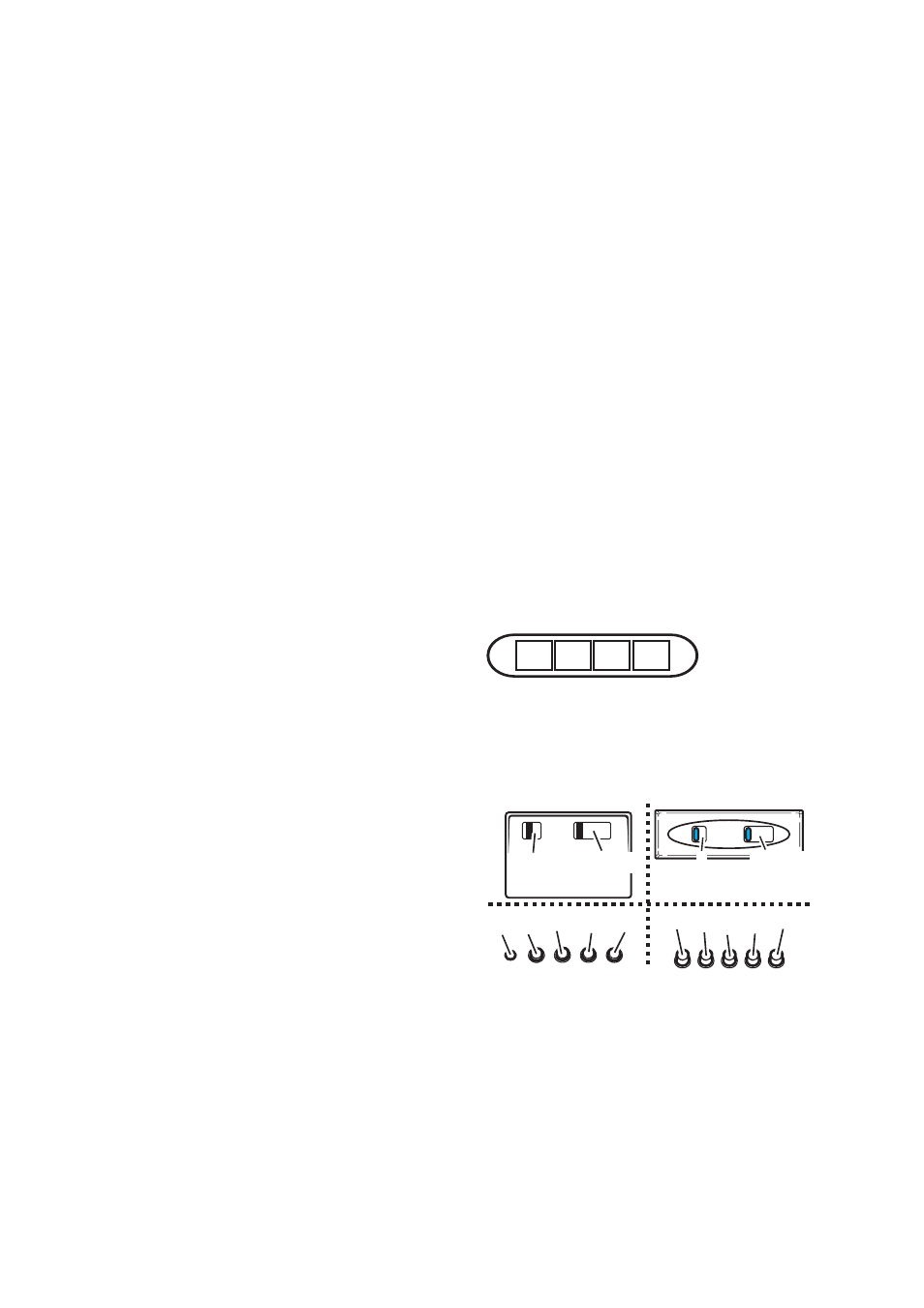
Functioning – Model with Keyboard
A
B
C
D
A. on/off light switch
B. on/off aspiration switch and minimum power selection
B+C. medium power selection aspiration switch
B+D. maximum power selection aspiration switch
a
a b-c d e
f
b-c-d-e
b-c-d-e
a
a b c d e
a. ON/OFF lighting
b. OFF motors
c. - d. - e. Minimum suction power (c.), medium (d.),
maximum (e.).
f. Operation warning light (where present).
Note: Some models only possess one suction Power.
Attention: the models with an electric valve are supplied with 3
keys:
(a) Light ON/OFF, (b) Electric Valve Closure and (c) Opening.