4 initial alignment – Flowserve HWX Worthington User Manual
Page 15
HWX USER INSTRUCTIONS ENGLISH - 07/14
Page 15 of 40
4.3.2 Steel foundation
When the pump unit is mounted directly on structural
steel frame, it shall be well supported by constructural
beams. It is recommended to check the natural
frequency of the steel frame, because it shall not
coincide with the pump speed. The exact horizontal
alignment is very important!
4.3.3 Concrete foundation
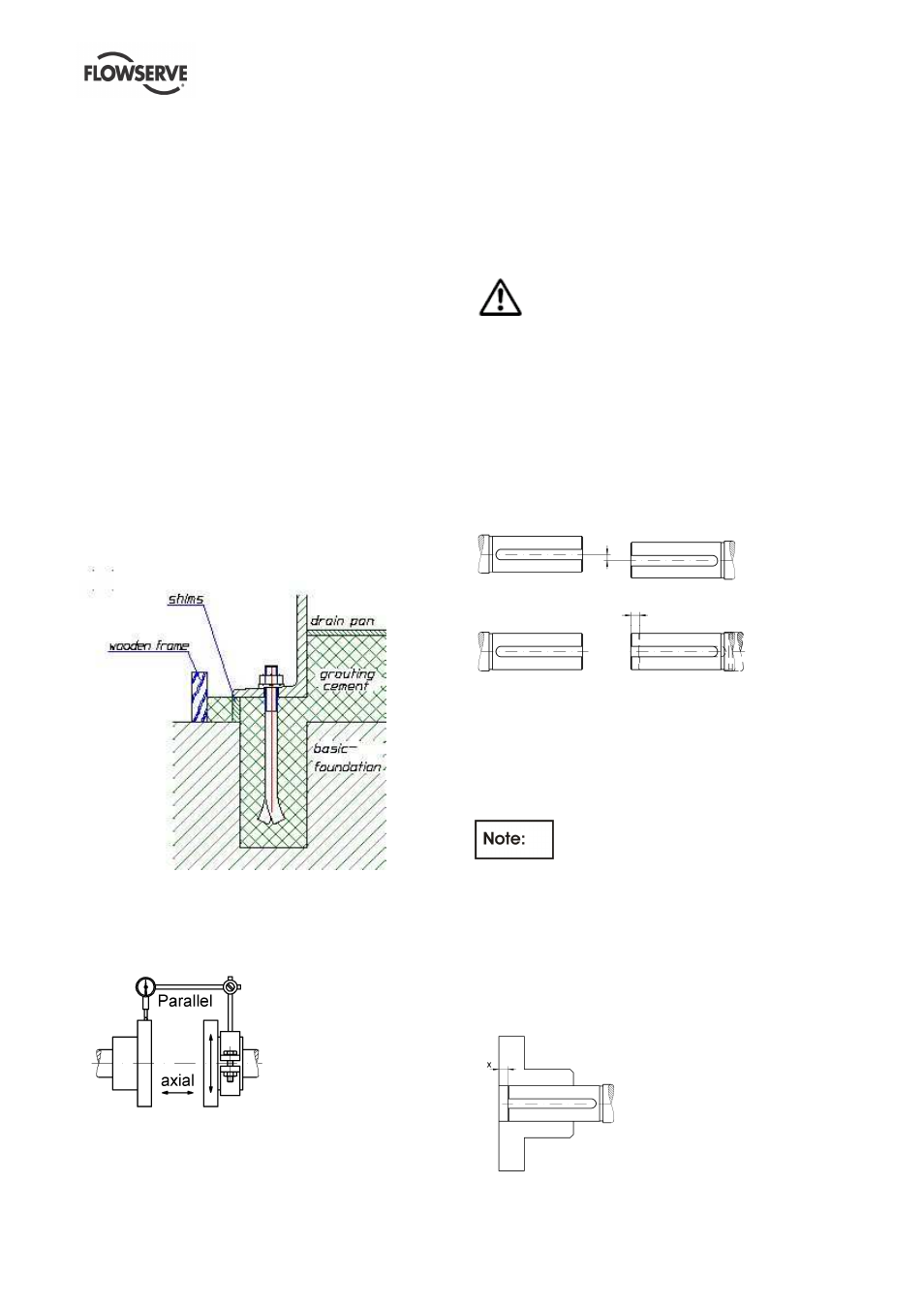
A concrete foundation must have an exact horizontal
alignment and must be placed on solid ground. First a
basic foundation shall be built with square shaped
holes for embedding the foundation bolts. After
putting the base plate into the foundation the proper
alignment can be obtained by adjusting it with shims
under the base plate. Now insert the foundation bolts
and grout the space between the basic foundation
and the base plate with grouting cement (refer to
illustration)
It is very helpful to use a properly made and stable
wooden frame around the base plate. So the grouting
cement will not flow side. When the grouting is totally
set and hardened the foundation bolts shall be
tightened in a firm and symmetrical way.
4.4 Initial alignment
The adjustment of motor and pump must be checked
(if necessary, make a new adjustment) before first
start up of the unit.
Ensure pump and driver are isolated electrically and
the half couplings are disconnected.
Align the motor to the pump, not the pump to the
motor. Alignment of the motor is achieved by using
the adjustment screws.
4.4.1 Permissible misalignment limits at working
temperature
When checking parallel alignment, the total indicator
read-out (TIR) shown is twice the value of the actual
shaft displacement.
The pump is only pre-aligned! Carefully check
and readjust alignment before start of the unit.
Take out the spacer of the coupling and check the
alignment of shafts end of pump and driver. The
maximum parallel offset should not exceed 0.05 mm
(0.002 in.)and the axially offset can be ± 1 mm (0.04
in.).
For more details refer to the manufacturer’s
instruction manual of coupling.
a)
b)
a) Parallel Offset: The median lines run parallel. The
maximum allowable parallel offset depends on
the size of coupling and is indicated in the
instruction manual of manufacturer of coupling
b) Axially Offset: Another offset is the displacement
of one or both of the shafts. A typical example is
thermal expansion.
The DBSE (distance between shaft ends)
is shown on the General Arrangement Drawing and is
larger than the length of the coupling spacer. This is
necessary to compensate all manufacturing
tolerances of line shafts and column pipes.
For installation of the coupling spacer the coupling
hub on the pump shaft must be axially moved to
match the spacer. This results in an axial clearance
"x" between coupling hub and shaft end, which is
taken into account by the coupling selection.