Flowserve HWX Worthington User Manual
Page 29
HWX USER INSTRUCTIONS ENGLISH - 07/14
Page 29 of 40
IMPELLER
HAND
GRINDER
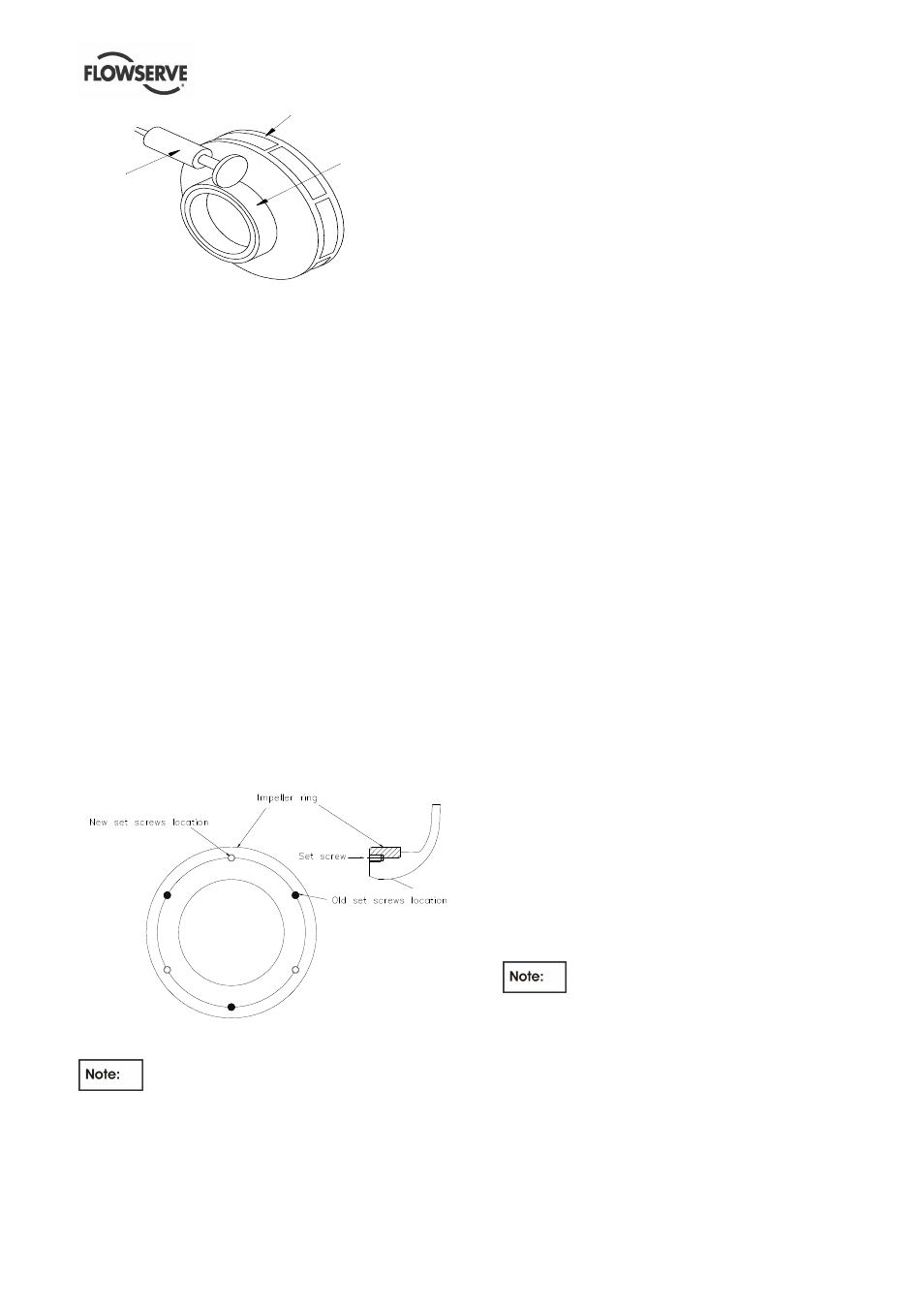
IMPELLER
RING
Figure 6.3
b) Determine that impeller has cooled to ambient
temperature by feeling with hand; then heat wear
ring using a torch until ring will slip into place on
impeller.
c) Verify trueness of wear ring to impeller fit as
outlined below or by an equivalent technique:
•
Make sure ring fits on impeller are free of
nicks or burrs. Heat new ring to 107 °C
(225 °F).
Set impeller with wear ring face up
on table of vertical lathe and parallel with
face of table.
•
Align centerline of impeller (that is, centerline
of impeller bore) with centerline of table using
bore as true surface for dial indicator.
Alignment should be within 0.03 mm (0.001
in.).
•
Clamp impeller in centered and parallel
position.
•
Set up dial indicator to run outside diameter
of wear ring ring and rotate table. Total runout
must not exceed 0.04 mm (0.0015 in.).
d) Drill and tap new holes in impeller spaced half the
circular distance
from the previously used holes in
the impeller. See sketch below (If tack welding
ring, use ER308 or ER309 rod and gas-tungsten
arc.
Figure 6.4
Impeller wear rings when installed must
be machined to establish original diameter and
running clearance. Whenever an impeller has new
wear rings fitted it must be dynamically balanced
before being reassembled. Refer to the Cross
Sectional drawing for the requested running
clearance.
6.8.1.2 Case wear rings (and casing cover wear
ring when fitted)
Each wear ring is locked against rotation with a
cylindrical pin.
a) To remove the wear ring, press it out. If this
method does not easily effect removal of the ring,
it can be split apart. First, however, drill one or
more holes in the face of the worn ring.
b) New rings to be installed must be shrunk by
freezing when installing in casing or casing cover.
See that temperature of casing / casing cover is
above 21 °C (70 °F).
c) Subcool new wear ring in dry ice to shrink it; then,
bottom ring squarely in bore of parent part by
using aluminium drift and mallet to strike evenly
around circumference of wear ring ring.
d) Determine that wear ring ring and parent part
have warmed to ambient temperature by feeling
with hand.
e) Verify trueness of wear ring-ring-to-part fit as
outlined below or by an equivalent technique:
•
Set up parent part in lathe or milling machine
so that register face of part can be used as
true side for dial indicator. The centreline of
part must be aligned with centreline of
machine's table and it must also be parallel
with table within 0.03 mm (0.001 in).
•
Set up dial indicator to run on inside diameter
of wear ring ring and rotate table (or chuck).
Total runout must not exceed 0.04 mm
(0.0015 in).
f) Fit and secure with a locking pin. Replacement
wear rings are furnished standard size in the
bore. Check the running clearance between
impeller and casing ring against the appropriate
value.
6.8.2 Checking Fit Between Impeller Bore and
Shaft.
The fit between the impeller bore and the shaft must
be correct or vibration is apt to occur.
To check the fit, proceed as follows:
a) Verify shaft straightness (See Section 6.7.5).
A three-point micrometer is the
preferred instrument for measuring bore; a stick
micrometer is its alternate. When measuring with
the three-point micrometer, measure close to the
keyway. With stick micrometer, measure three
places at 120-degree intervals.
b) Determine nominal fit of impellers with shaft:
•
by using micrometers to measure diameter of
bore under thickest metal near each end of
keyway of impeller and the corresponding
diameter of shaft,