5 piping, 6 electrical connections – Flowserve HWX Worthington User Manual
Page 16
HWX USER INSTRUCTIONS ENGLISH - 07/14
Page 16 of 40
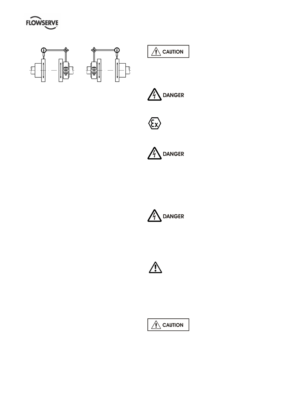
How the alignment of the coupling should be done
you can see on the sketches and explanations below!
a)
b)
a) Fix the dial gauge on the driven shaft and check
the concentricity by turning of both hubs; correct it if
necessary.
b) Fix the dial gauge on the driving shaft and check
the concentricity by turning of both hubs; correct it if
necessary.
If the pump is handling hot liquid, the alignment must
be rechecked in warm condition of the unit.
4.5 Piping
4.5.1 General
Protective covers are fitted to the pipe connections to
prevent foreign particles entering during
transportation and installation. Ensure that these
covers are removed from the pump before connecting
any pipes.
Maximum forces and moments allowed on the pump
flanges vary with the pump size and type. To
minimize these forces and moments which may
cause misalignment, hot bearings, worn couplings,
vibration and a possible failure of the pump, the
following points shall be strictly followed:
a) Prevent excessive external pipe load.
b) Do not connect piping by applying external force
(use of wrenches, crane,...). Piping shall be
aligned without residual stress.
c) Do not mount expansion joints so that their force,
due to internal pressure, acts on the pump flange.
Fitting an isolator and non-return valves can allow
easier maintenance. Never throttle pump on suction
side and never place a valve directly on the pump
inlet nozzle.
A non-return valve shall be located in the discharge
pipework to protect the pump from excessive back
pressure and hence reverse rotation when the unit is
stopped.
Piping and fittings shall be flushed before use. To
avoid damages of the pump install a Y-strainer or a
strainer of 40 mesh.
Piping for corrosive liquids shall be arranged to allow
pump flushing before removal of a unit.
4.5.2 Drain
This connection is used for total drainage of the pump
casing. A flanged drain is standard and can be
optionally equipped with various kinds of valves.
Refer to GA drawing for details of the drain
connection.
By pumping toxic or explosive
media, provide the necessary security actions, e.g.
flushing with nitrogen.
4.6 Electrical connections
Electrical connections must be made by a qualified
Electrician in accordance with the relevant local
national and international regulations.
It is important to be aware of the EUROPEAN
DIRECTIVE on hazardous areas where compliance
with IEC60079-14 is an additional requirement for
making electrical connections.
It is important to be aware of the EUROPEAN
DIRECTIVE on electromagnetic compatibility when
wiring up and installing equipment on site. Attention
must be paid to ensure that the techniques used
during wiring/installation do not increase
electromagnetic emissions or decrease the
electromagnetic immunity of the equipment, wiring or
any connected devices. If in any doubt contact
Flowserve for advice.
The motor must be wired up in accordance with the
motor manufacturer's instructions (normally supplied
within the terminal box) including any temperature,
earth leakage, current and other protective devices
as appropriate. The identification nameplate should
be checked to ensure the power supply is
appropriate.
A device to provide emergency stopping must
be fitted.
If not supplied pre-wired to the pump unit the
controller/starter electrical details will also be supplied
within the controller/starter.
For electrical details on pump sets with controllers
see the separate wiring diagram.
See section 5.3, Direction of
rotation before connecting the motor to the electrical
supply.