4 electrical connections – Flowserve MENBLOC User Manual
Page 19
MENBLOC USER INSTRUCTIONS ENGLISH 71576296 - 02/13
Page 19 of 40
flowserve.com
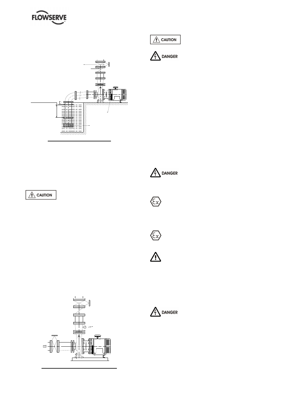
4.3.2.2 Design of a suction lift line
The inlet pipe must be as short and as direct as
possible, never place an elbow directly on the
pump inlet nozzle.
Valve
Non-return valve
IM M E RS IO N : I
SUFFICIEN T
M E NBLO C
Inlet-strainer
I
≥
3 x D
Sump suction configuration
a) Avoid sharp elbows or sudden changes of
diameter. Use reducers with
≤
20° total angle.
b) Arrange that the suction piping is inclined
upwards towards the pump ensuring that there
are no peaks.
c) If a foot valve is necessary, do not oversize it
because it would generate pulsations (valve
hammering).
Do not tighten flanges before the
final check (see § 4.3.4).
4.3.3 Discharge piping
4.3.3.1 Design of a discharge line
a) If discharge line is provided with a divergent,
its total angle will be between 7° and 12°.
b) Install the discharge valve after the non-return
valve downstream.
The non-return valve will be set in the discharge
pipe to protect the pump from any excessive
pressure surge and from reverse rotation.
If necessary, a pressure gauge or pressure sensor
for pump or system control can be connected on
the piping
Control
manometer
Installation of control manometer
Do not tighten flanges before the
final check (see § 4.3.4).
Never wire up the electric motor
before the pump installation has been completely
finished.
4.3.4 Final checks
a) Check the tightening of anchor bolts. Tighten
them if necessary.
b) Check that protective covers on suction and
discharge flanges are removed.
c) Check that holes of piping flanges are parallel
and correspond to those of the pump.
d) Tighten suction and discharge flanges.
e) If it is required, connect piping (hydraulic,
pneumatic, sealing system).
f) Check seal and the working of auxiliary piping.
4.4 Electrical connections
4.4.1 Safety conditions about electrical
connections
Electrical connections must be made
by a qualified Electrician in accordance with
relevant local national and international
regulations. This includes any grounding.
It is important to be aware of the
EUROPEAN DIRECTIVE on potentially explosive
areas where compliance with IEC60079-14 is an
additional requirement for making electrical
connections.
Avoid mechanical, hydraulic or electrical
overload by using motor overload trips or a power
monitor and make routine vibration monitoring.
It is important to be aware of the EUROPEAN
DIRECTIVE on electromagnetic compatibility when
wiring up and installing equipment on site. Attention
must be paid to ensure that the techniques used
during wiring/installation do not increase
electromagnetic emissions or decrease the
electromagnetic immunity of the equipment, wiring or
any connected devices. If in doubt, contact
Flowserve for advice.
If the pump assembly has been
stored or is located in a damp atmosphere, the
isolating resistance of the electric motor must be
checked by a qualified electrician before wiring up.
The resistance must be greater than 5000 ohms
per volt specified on the motor nameplate.
Carry out the ground connections according to the
current local regulations.