7 assembly – Flowserve MENBLOC User Manual
Page 31
MENBLOC USER INSTRUCTIONS ENGLISH 71576296 - 02/13
Page 31 of 40
flowserve.com
6.7 Assembly
6.7.1 Reassembly of the MENBLOC unit
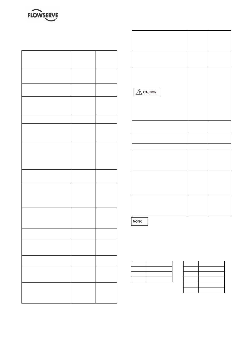
REASSEMBLY OPERATIONS
MENBLOC
WITH AN
ADDED
PUMP SHAFT
MENBLOC
WITH AN
EXTENDED
MOTOR
SHAFT
Fit the [2110] pump shaft on
the motor shaft end with its
[6700-01] key
X
Screw and tighten the [6570]
screw in the hole of the motor
shaft end
X
Put the motor vertically shaft
end upwards. Take
precautions not to damage the
fan cover
X
X
Put the [9331] shield grid into
the cover for motor casing
X
Mount the lantern bracket
[3180] on the motor. Screw
and tighten the [6577-03] bolts
and the [6581] hexagon nuts
X
Mount the [1221] casing cover
with stuffing box on the [3130]
cover of motor casing and
respect the orientation (the 2
casing cover ribs facing the 2
oblong holes of the cover for
motor casing)
X
Mount the [1221] casing cover
on the [3180] lantern bracket
and respect the orientation
X
For an unclamped casing
cover: screw and tighten the
[6577-02] bolts with an
appropriate wrench tightening
opposing bolts and working
around the casing
X
X
Put the fixed ring of the [4200]
mechanical seal into soapy
water and mount it in the
casing cover with the tools
defined in § 6.5
X
X
Plunge rotating ring into soapy
water
X
X
Mount the complete stationary
ring, the spring and the seat of
the [4200] mechanical seal by
using the tools defined in § 6.5
X
X
Mount the [6700] or [6700-02]
key
X
X
Mount the [2250] impeller on
the shaft end and avoid
damaging the mechanical seal
seat
X
X
Mount the [2905] plain washer.
Screw and tighten the [2912]
shaft end nut with an
appropriate key (fix the rotor in
position)
X
X
REASSEMBLY OPERATIONS
MENBLOC
WITH AN
ADDED
PUMP
SHAFT
MENBLOC
WITH
EXTENDED
MOTOR
SHAFT
Mount the [4590-03] special ring
on the casing cover. Mount the
pump shaft and respect the
orientation
X
X
Screw the [6577-01] or [02] bolts.
Tighten opposing bolts working
around the cover with an
appropriate wrench (do not use a
striking-face wrench)
For MENBLOC
80-65-125, 80-65-160, 80-65-200L,
100-80-160, 100-125-250L, the
[6577-01] bolts have to be
mounted with sealing product
LOCTITE pipe sealant 577 or
similar.
X
X
Check the correct rotation of the
rotor with an appropriate key at the
shaft end
X
X
Reinstall the unit according to the
rules defined in this manual
X
X
TO REINSTALL DIRECLY THE ELECTRIC MOTOR
The [6570] screw stays in the shaft
threading but does not hinder the
assembly, install the motor, mount
and block the [6577-03] bolts and
the [6581] nuts
X
Push on the pump shaft end
without shocks or blows until the
pump shaft presses against the
shoulders of the motor shaft.
Tighten the [6570] screw. (see the
following fig. 1)
X
To avoid loosening of the screw
during the running of the pump use
a nut locking compound, after
having pain carefully degreased
the screw and the threading
X
These recommendations correspond to a
complete assembly and to a complete dismantling.
For a partial dismantling, only certain areas will be
relevant.
The torques to be applied are:
Casing / casing Cover /
Lantern [6577]
Self-locking [2912]
m.daN (lbf.ft)
m.daN (lbf.ft)
M10
3 (22)
M10
3 (22)
M12
5 (37)
M12
6 (44)
M16
11 (81)
M14
8 (59)
M18
12 (89)
M20
14 (103)
The tightening torques have been calculated as a
function of the forces produced by the pumps.
These torques correspond to a tension of the shaft
end of 25 % to 50 % of the elastic limit.
The tolerance allowed on the tightening torques is
±
30 %.