3 general arrangement drawing – Flowserve MENBLOC User Manual
Page 36
MENBLOC USER INSTRUCTIONS ENGLISH 71576296 - 02/13
Page 36 of 40
flowserve.com
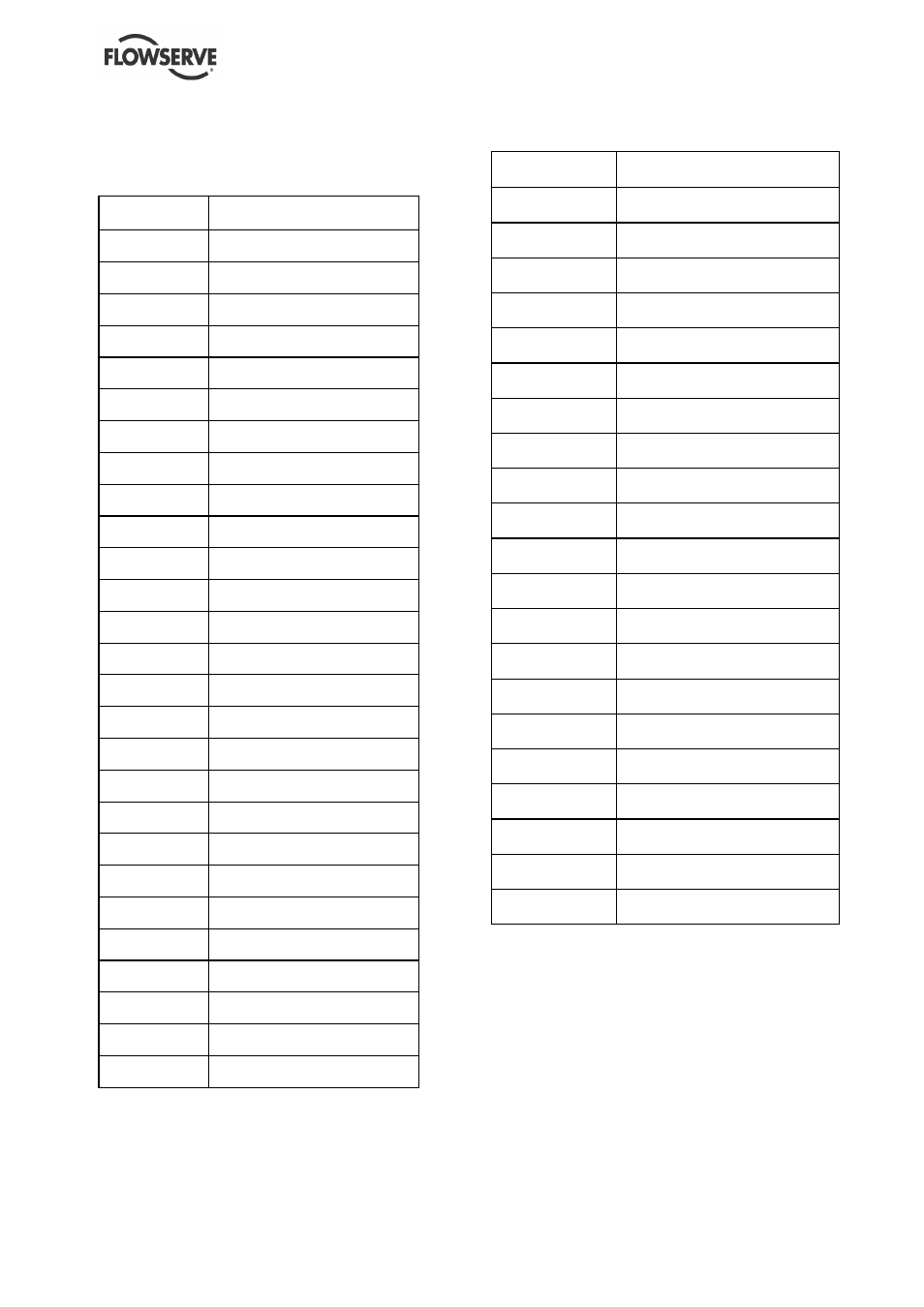
8.2 Sectional drawings part list
8.2.1 MENBLOC with an extended motor shaft
ITEM
PARTS LIST
1110
Pump casing
1221
Casing cover
2250
Impeller
2540
Thrower
2905-01
Plain washer
2905-02
Curved spring washer
2912
Self-locking nut
3011-01
Radial ball bearing ( Drive end)
3011-02
Radial ball bearing ( Non-drive
end)
3130
Motor end shield
4200
∗
Mechanical seal
∗
4212
Spacer
4590-01
∗
Gasket
∗
4590-02
∗
Gasket
∗
4590-03
∗
Casing joint
∗
6511
Priming plug
6515
Drain plug
6577-01
Hexagon bolt
6577-02
Hexagon bolt
6700
Key
8010
Motor
8125
Rotor
8140
Wound stator
8161
Fan
8162
Fan cover
8170
Terminal box
9331
Cover plate
8.2.2 MENBLOC with added pump shaft
ITEM
PARTS LIST
1110
Pump casing
1221
Casing cover
2110
Pump shaft
2250
Impeller
2905
Plain washer
2912
Self-locking nut
3180
Lantern bracket
4200
∗
Mechanical seal
∗
4590-01 *
Gasket
∗
4590-02
∗
Gasket
∗
4590-03
∗
Casing joint
∗
6511
Priming plug
6515
Drain plug
6570
Screw with dog point
6577-01
Hexagon bolt
6577-02
Hexagon bolt
6577-03
Hexagon bolt
6581
Hexagon nut
6700-01
Key (motor)
6700-02
Key
8010
Motor
8.3 General arrangement drawing
The typical general arrangement drawing and any
specific drawings required by the contract will be sent
to the Purchaser separately unless the contract
specifically calls for these to be included into the
User Instructions. If required, copies of other
drawings sent separately to the Purchaser should
be obtained from the Purchaser and retained with
these User Instructions.