6 disassembly, Flowserve – Flowserve MENBLOC User Manual
Page 30
MENBLOC USER INSTRUCTIONS ENGLISH 71576296 - 02/13
Page 30 of 40
flowserve.com
6.6 Disassembly
Refer to section 1.6, Safety, and section 6
Maintenance, before dismantling the pump.
Before dismantling the pump for
overhaul, ensure genuine Flowserve replacement
parts are available. Refer to sectional drawings for
part numbers and identification.
REPAIR OF THE PUMP
If the pump presents abnormalities or a
persistent malfunction, contact immediately:
FLOWSERVE
After-sales Service
Tel.: 02 43 40 57 57
(33) 2 43 40 57 57
Fax.: 02 43 40 58 17
(33) 2 43 40 58 17
Assembly and disassembly must
be carried out by FLOWSERVE personnel or its
approved repairers whose list may be sent on
request. It is obvious that the following instructions
and recommendations cannot replace their
knowledge and experience.
a)
NEVER DO MAINTENANCE
WORK WHILST THE UNIT IS CONNECTED
TO POWER.
b)
DRAIN PUMP AND ISOLATE PIPING
BEFORE DISMANTLING THE PUMP.
The pump should be disassembled only if certain
signs of anomalies or malfunction are observed.
Disassemble only to the extent that the cause of
the problem may be reached.
In any case, the disassembly must be carried out
by qualified personnel who have read the
instructions of the leaflet and in particular the
safety instructions.
Disassembly must be done with great care to
avoid damage to the pumps internal parts. To
make reassembly easier, display parts in the
disassembly order. Protect all machined surfaces
from metal/metal contacts and from corrosion.
Before any disassembly it is imperative to:
a) Close the outlet and inlet valve.
b) Wait until the pump casing is at ambient
temperature.
c) Be sure that the pump casing is not under
pressure.
6.6.1 Dismantling of the MENBLOC unit pump
end
DISMANTLING OPERATIONS
MENBLOC
WITH
ADDED
PUMP
SHAFT
MENBLOC
WITH
EXTENDED
MOTOR
SHAFT
Unscrew the [6577-01] hexagon
bolts and remove the motor and
rotor unit from the pump casing
X
X
Unscrew the [2912] self-locking
nut, remove the [2905] plain
washer, the [2250] impeller, the
[6700] key and the [4200]
mechanical seal
X
X
If necessary unscrew the [6577-
02] hexagon bolts to withdraw
the cover for motor casing
X
If necessary unscrew the [6577-
02] hexagon bolts to withdraw
the casing cover of the lantern
bracket
X
Remove the [6570] screw and
withdraw the pump shaft
X
TO REMOVE DIRECTLY THE MOTOR FROM
THE PUMP UNIT
Unscrew the [6570] screw by
introducing the key into one of
the oblong holes of the lantern
X
Unscrew the [6577-03] hexagon
bolts and remove the motor
X
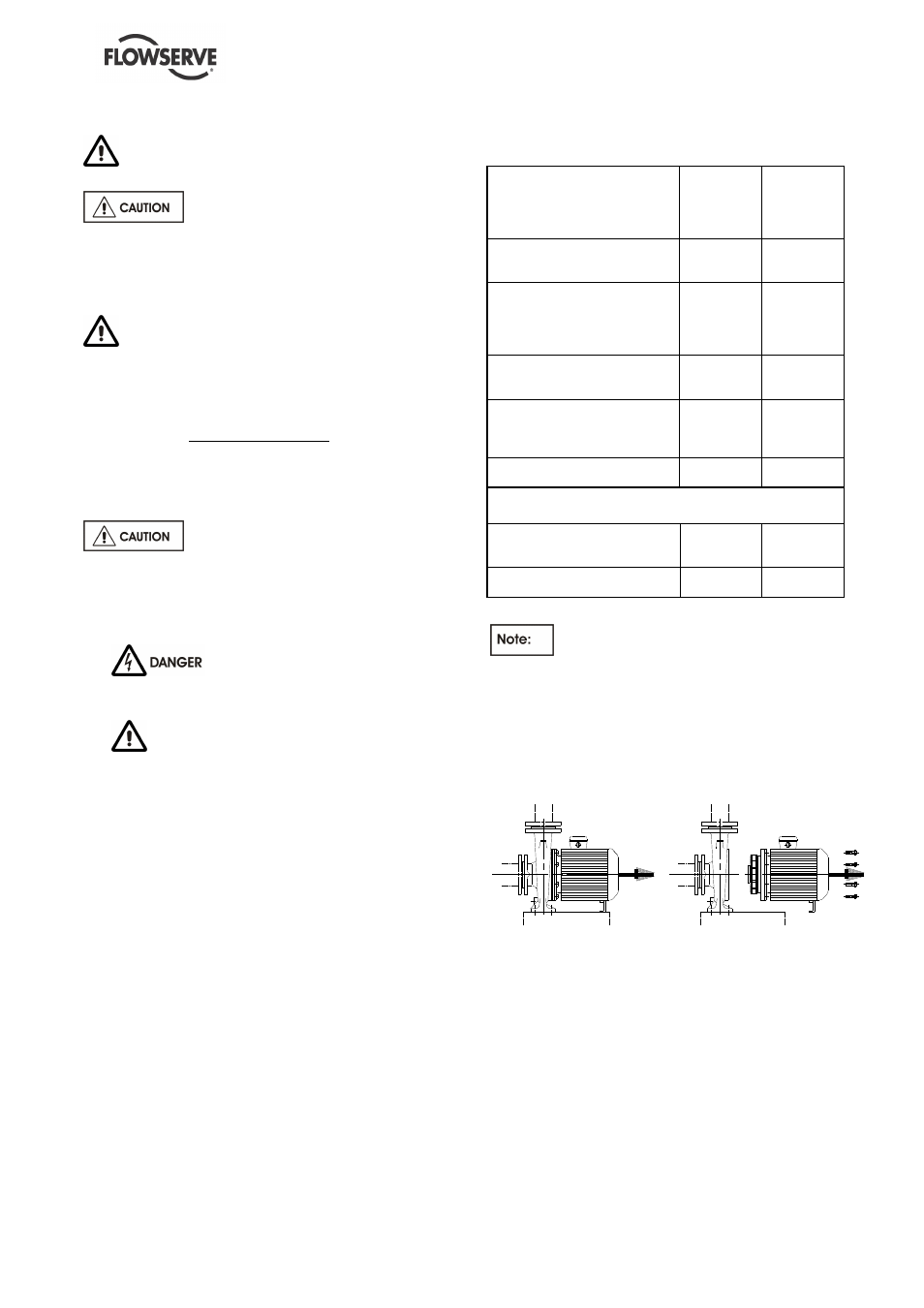
For the MENBLOC unit with an extended
motor shaft, it is possible to directly withdraw the
motor without dismantling the impeller and the
mechanical seal.
The drawings represented in chapter 8 of this
notice locate the mentioned components by their
part number [ ].
It is possible to disassemble the motor and rotor
unit from the pump casing without disconnecting
the casing from the piping.
To achieve this unscrew the bolts part number
[6577-01].
The MENBLOC pump unit with an added pump
shaft is fitted with an IP 55 motor.
The MENBLOC pump unit with an extended motor
shaft is fitted with an IP 55 motor.