Flowserve VTP Wet Pit User Manual
Page 28
VERTICAL TURBINE PUMPS (VTPS) CENTRIFUGAL PUMPS ENGLISH 71569224
– 10-13
Page 28 of 76
flowserve.com
Installation of non-adjustable flanged
4.5.3.3
coupling WNA/PNA.
Follow procedure from (a) thru (e) as listed in section
4.5.4.1.
f) Install one set of split thrust rings [312A] in to the
circular keyway in pump shaft. Pull up the pump
half of the coupling [44] over the split keys.
g) Slide driver half coupling [42] onto driver shaft in
the same manner as the pump half of the
coupling.
h) Set the spacer ring [314] between the two halves
of the coupling together. Tighten all cap screws
[364] evenly to the bolt torques as listed in
4.5.4.1 under item (m).
i) Proceed with the driver installation.
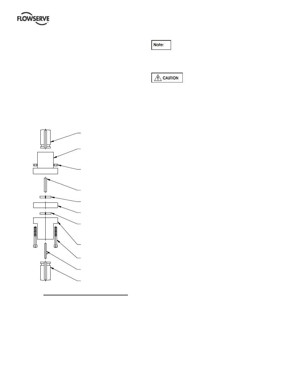
TYPE-WNA/PNA COUPLING DETAILS
Installation of drivers
4.5.4
Drivers will come with either hollow shaft or
solid shaft as specified on the order/contract.
Choose the correct installation procedure from the
following paragraphs.
Reverse rotation with the pump shaft
connected can cause extensive damage to the pump.
Always check rotation before connecting driver to
pump.
Installation of hollow shaft driver
4.5.4.1
a) Clean driver mounting flange on discharge head
and check for burrs or nicks on the register and
mounting face. Oil lightly.
b) Remove driver clutch.
c) See (j) regarding installation of motor guide
bushing, if required.
d) Lift driver and clean mounting flange, checking for
burrs and nicks.
e) Center motor over pump and rotate to align
mounting holes.
Electric motors - rotate junction box into desired
position.
Gear Drives - rotate input shaft into desired
position.
f) Lower carefully into place making certain that the
female register on the driver mates over the male
register on the pump.
g) Bolt driver to discharge head.
h) Check the driver manufacturer's instruction
manual for special instructions including
lubrication instructions and follow all "startup"
directions.
i) Electric motors should be checked for rotation at
this time. Make certain the driver clutch has been
removed. Make electrical connections and
"bump" motor (momentarily start, then stop) to
check rotation. DRIVER MUST ROTATE
COUNTERCLOCK-WISE when looking down at
top end of motor. To change the direction of
rotation on a three-phase motor, interchange any
two line leads. To change direction of rotation on
a two phase motor, interchange the leads of either
phase
j) Some motors will be supplied with a "lower guide
bushing" or "steady bushing" which is installed at
the bottom of the motor to stabilize the shaft at this
point. Some motor manufacturers mount this
guide bushing before shipping while others will
ship the guide bushing with instructions for field
mounting.
MOTOR SHAFT
(42) DRIVER COUPLING
(363) HEX NUT
(46A) DRIVE KEY
(312A) SPLIT THRUST
(314) SPACER RING
(312A) SPLIT THRUST
(44) DRIVEN COUPLING
(364) CAP SCREW
(46) KEY ASSEMBLY
(12A) TOP SHAFT
HALF
RING
RING
HALF