Flowserve VTP Wet Pit User Manual
Page 29
VERTICAL TURBINE PUMPS (VTPS) CENTRIFUGAL PUMPS ENGLISH 71569224
– 10-13
Page 29 of 76
flowserve.com
k) Check the packing slip to see if a guide bushing is
required, if so, determine if the bushing is already
mounted or not and proceed accordingly. Refer to
motor instruction manual.
l) Carefully install drive clutch on driver making sure
that it fits down properly.
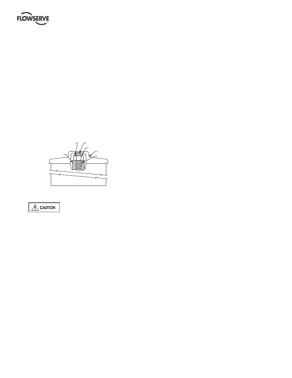
m) Clean threads on top of head shaft and head shaft
nut. Lubricate male threads lightly. Install head
shaft.
n) Install gib key [335] in clutch and shaft. This must
be a sliding fit and may require filing and dressing.
Do not force.
o) Thread adjusting nut down on shaft until it bears
against clutch. (Threads on 43 mm (1.68 in.) and
larger head shaft adjusting nuts are left-handed
and all others are right handed). Do not thread
nut further at this time. See impeller adjusting
instructions in section 5.3.
Installation of solid shaft driver without
4.5.4.2
jacking screws
When lowering the motor and driver
half of coupling onto pump, do not let pump half of
the coupling touch the driver half of the coupling.
Before bumping motor make sure coupling halves
are not touching and that the driver can rotate freely,
without rotating the pump
Driver half coupling must be in proper position so the
circular key will not come out.
a) Clean driver mounting flange on discharge head
and check for burrs or nicks on the register and
mounting face. Oil lightly.
b) Center motor over pump and rotate to align
mounting holes.
Electric motors: Rotate junction box into desired
position.
Gear Drives: Rotate input shaft into desired
position.
c) Lower driver carefully into place making certain
that the female register on the driver mates over
the male register on the pump.
d) Bolt driver to discharge head.
e) Check driver manufacturer's instructions for
special instructions including lubrication
instructions and follow all "startup" instructions.
f) Electric drivers should be checked for rotation at
this time. Make electrical connections "bump"
motor (momentarily start, then stop) to check
rotation. DRIVER MUST ROTATE
COUNTERCLOCKWISE when looking down at
top end of motor. To change the direction of
rotation on a three-phase motor, interchange any
two line leads. To change direction of rotation on
a two-phase motor, interchange the leads of either
phase.
g) See impeller adjustment instructions (section 5.3)
before bolting the pump and driver half of the
coupling together.
Installation of solid shaft driver with
4.5.4.3
jacking screws
a) Clean driver mounting flange on discharge head
and check for burrs or nicks on the register and
mounting face. Oil lightly.
b) Center motor over pump and rotate to align
mounting holes.
Electric motors: Rotate junction box into
desired position.
Gear Drives: Rotate input shaft into desired
position.
c) Lower driver carefully into place. Mount the dial
indicator base on the O.D. of the motor half
coupling. Set the indicator on the pump shaft,
position the dial to zero being careful that the
indicator is in direct line with one of the
jackscrews. Record this reading then rotate the
motor shaft and indicator 180 degrees. Record
this reading being careful to note plus or minus
values. Take the difference of the two readings
and using the jackscrews move the motor one-
half of the difference. Repeat this step until the
T.I.R. reading is a maximum of 0.051mm
(0.002in.). Then repeat this step for the set of
jack screws located 90 degrees to the first set.
Once all readings are within 0.051mm (0.002in.),
tighten motor bolts and check for any movement
in readings.
d) Check driver manufacturer's instructions for
special instructions including lubrication
instructions and follow all "startup" instructions.
e) Electric drivers should be checked for rotation at
this time. Make electrical connections and
"bump" motor (momentarily start, then stop) to
check rotation. DRIVER MUST ROTATE
COUNTER-CLOCKWISE when looking down at
top end of motor. To change the direction of
rotation on a three-phase motor, interchange any
(334) LOCK SCREW
COUPLING
HEAD SHAFT (10)
HEAD SHAFT NUT (66)
DRIVER
GIB KEY(335)