Flowserve VTP Wet Pit User Manual
Page 40
VERTICAL TURBINE PUMPS (VTPS) CENTRIFUGAL PUMPS ENGLISH 71569224
– 10-13
Page 40 of 76
flowserve.com
Impeller adjustment for a solid shaft
5.3.2
driver
Impeller adjustment when using solid shaft drivers is
accomplished in the adjustable flanged coupling
located below the driver.
Adjusting adjustable flanged coupling
5.3.2.1
a) Assemble coupling on pump shaft and driver
shaft (if not installed earlier).
b) Check motor direction of rotation.
c) Check and write down Flowserve recommended
impeller setting for final adjustment.
d) Pump to motor alignment and final coupling
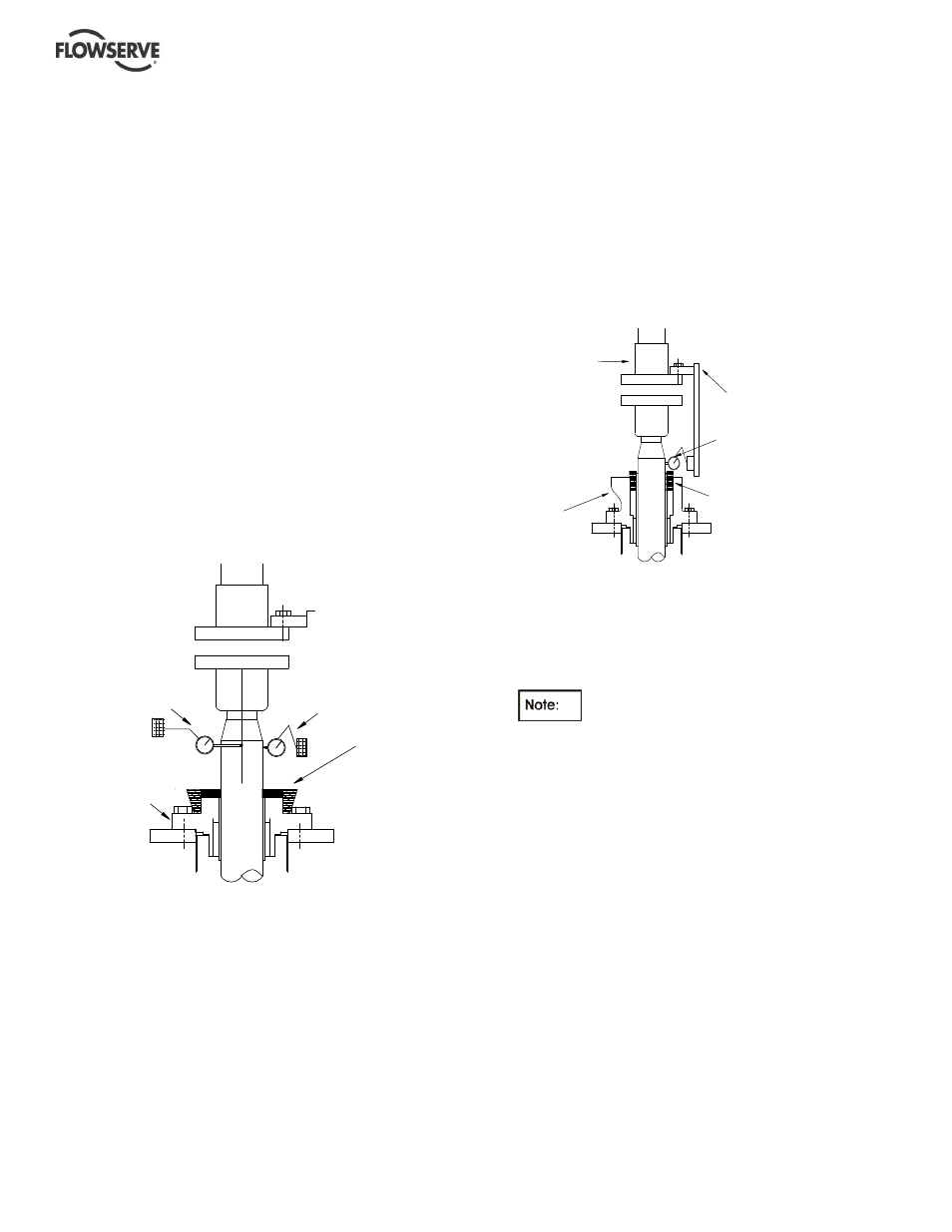
Mount two magnetic indicator bases on the
discharge head at 90 degrees to each other
Set the indicator tips on the shaft just above
the seal and at 90 degrees to each other.
(Usually parallel and perpendicular to the
discharge nozzle) push the shaft (parallel to
discharge) back and forth (without bending
shaft)
Note and record the minimum and maximum
indicator readings. Do the same procedure
at 90 degrees to the discharge
Set the shaft in the center of the maximum
and minimum indicator readings both
directions. If the shaft will not stay in this
position, use small wooden wedges between
the shaft and seal bolts to hold the shaft.
The indicators can now be removed
Alternate method for pump with packing:
Using an inside micrometer, measure the
space between the shaft and the packing box
bore. Do this both parallel and perpendicular
to the discharge nozzle
Using the wedges center the shaft so the
measurements taken at 180 degrees to each other are
within 0.10 mm (0.004 in.) of being equal
(For pumps using jackscrews for motor go to
step f).
e) Mount the magnetic base on the drive half
coupling (a band clamp may be necessary to hold
base due to limited space). Position the tip of the
indicator on the pump shaft just above the seal.
Slowly rotate the driver shaft.
Note and record the T.I.R. reading. If this reading
is more than 0.25 mm (0.010 in.) for WA and WSA
couplings or 0.15 mm (0.006 in.) for PA and PSA
couplings, unbolt the drive and reposition the
driver in the direction required to reduce the T.I.R.
to within the allowable limits.
If a register fit is used for alignment,
driver will be able to be moved only a few
thousandths of an inch. If enough movement is
not obtainable then the male register can be filed
to obtain acceptable T.I.R. readings (Go to step
g).
f) On pumps using jackscrews for motor alignment,
mount the dial indicator base on the O.D. of the
motor half coupling. Set the indicator on the shaft,
position the dial to zero being careful that the
indicator is in direct line with one of the
jackscrews. Record this reading then rotate the
motor shaft and indicator 180 degrees.
Record this reading being careful to note plus or
minus values. Take the difference of the two
readings and using the jackscrews move the
motor one half of the difference. Repeat this step
until the T.I.R. reading is a maximum of 0.05 mm
(0.002 in.).
IF NEEDED
INSERT
PACKING
PIECES/WEDGES
ALL AROUND
TO CENTER
THE SHAFT
DIAL
INDICATOR #1
DIAL
INDICATOR #2
MECHANICAL
SEAL
CENTER SHAFT IN STUFFING
BOX USING FOUR WOOD OR
METAL WEDGES
DIAL INDICATOR
RIGID BRACKET
SECURE WITH TWO BOLTS
STUFFING BOX
EXTENSION
MOTOR HALF
COUPLING