Flowserve CPX IDP User Manual
Page 15
CPX, CPXR, CPXN and CPXP USER INSTRUCTIONS ENGLISH 71569117 09-11
Page 15 of 44
flowserve.com
NPSH margin is not large, it is recommended that
the pipe straight is 5 to 10 pipe diameter. (See
section 10.3, Reference 1.) Inlet strainers, when
used, should have a net 'free area' of at least three
times the inlet pipe area.
e) Fitting isolation and non-return valves will allow
easier maintenance.
f) Never throttle pump on suction side and never
place a valve directly on the pump inlet nozzle.
4.6.2.2
CPXP suction piping
a) The inlet pipe should be as short as possible,
airtight and the smallest volume as practical for
the pump flow rate so as to enable quick priming.
Where inlet pipe volume is large an inlet foot
valve is recommended to retain the liquid in the
suction piping and thus reduce the subsequent
priming time.
b) It is recommended that the pump inlet pipe is no
larger than the pump inlet bore or such that the
suction velocity is in the range of 3 to 5 m/sec
(10 to 16 ft/sec). The piping should slope down
towards the pump casing suction flange.
c)
Take the suction lift into account in
the available NPSH, which must be higher than the
required NPSH of the pump.
d) Allow a minimum of two pipe diameters of straight
section between the elbow and inlet flange.
e) Fitting an isolation valve will allow easier
maintenance.
f)
Never throttle pump on suction side and never
place a valve directly on the pump inlet nozzle.
4.6.3 Discharge piping
4.6.3.1
CPX, CPXR and CPXN discharge piping
a) A non-return valve should be located in the
discharge pipework to protect the pump from
excessive back pressure and hence reverse
rotation when the unit is stopped.
b) Fitting an isolation valve will allow easier
maintenance.
4.6.3.2
CPXP discharge piping
a) In order to minimize friction losses and hydraulic
noise in the pipework it is good practice to choose
pipework that is one or two sizes larger than the
pump discharge. Typically main pipework velocities
should not exceed 3 m/s (9 ft/sec) on the discharge.
Pipework expanders should have a maximum angle
of divergence of 9 degrees.
b) If a non-return valve is located in the discharge
pipework then a vent/bleed pipe should be fitted
from the discharge pipe back to the sump or
source tank.
c) A regulating valve should be fitted in the discharge
pipework unless pump flow is controlled by the
delivery system design.
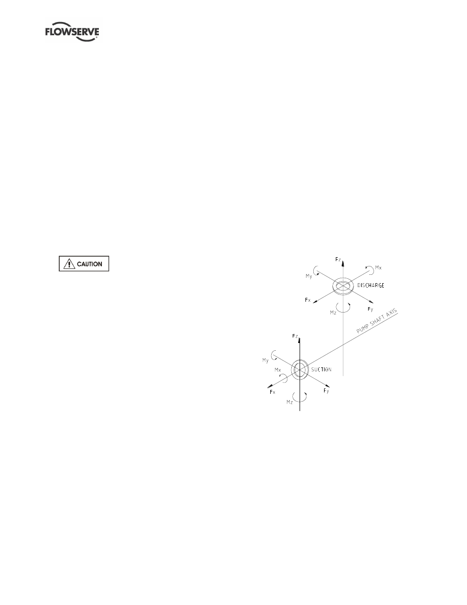
4.6.4 Allowable nozzle loads
The pump complies with ISO 5199 shaft deflection
limits for the following flange loads. The values are
presented in the ISO 5199/ISO 13709 (API 610)
format. Please note that the values permitted may be
higher or lower than those in ISO 5199; see those
specified for the actual pump size.
The values permitted (50 mm and above) meet ISO
13709 (API610) Table 4 values with grouted metallic
baseplates. Individual forces and moments up to
twice ISO 13709 (API610) Table 4 values may be
permitted but only when applied in accordance with
the conditions in ISO 13709 (API610) Annex F.
Values are presented in compliance with the ISO
1503 sign convention.
All individual values which are greater than the following
values must be referred to Flowserve for approval.