Flowserve CPX IDP User Manual
Page 30
CPX, CPXR, CPXN and CPXP USER INSTRUCTIONS ENGLISH 71569117 09-11
Page 30 of 44
flowserve.com
j)
Fit O-ring [4610.2] on the bearing carrier. Lightly
lubricate the bearing carrier bore and O-ring.
k) Ensure the shaft keyway edges are free of burrs.
During installation, use tape or similar over the
keyway to avoid damaging the drive side bearing
seals.
l)
Slide the bearing carrier [3240] onto the
shaft/bearing assembly and insert bearing circlip
[6544] into the carrier groove or screw up the
bearing locknut [3712.2].
m) On grease lubricated pumps, pump grease
through the grease nipple in the bearing carrier
[3240] until grease is visible in the bearing races.
n) Check shaft [2100] for free rotation.
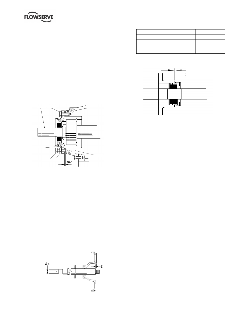
o) Install the shaft assembly into the bearing housing
[3200] until the gap is approx. 5 mm (0.2 in.).
2100
6570.2
3240
6570.3
6580.1
3200
p) Fit the bearing carrier screws [6570.2] but do not
tighten.
q) Fit the labyrinth ring [4330] (if used) into the
bearing housing ensuring the drain hole faces the
bearing and is at the 6 o'clock position.
r) Press drive side liquid deflector [2540.1] and
pump side liquid deflector [2540.2] onto shaft
where applicable. These should be set 0.5 to 2
mm (0.02 to 0.08 in.) (light contact for elastomer
type) from the bearing carrier and bearing
housing respectively.
s) The pump side deflector [2540.2] (this feature is
integral with some proprietary labyrinth seals)
should only be set in its final position after setting
the shaft axial position.
t)
Temporarily fit the cover [1220] to the bearing
housing. The shaft [2100] may now be positioned
in relation to the cover face, as shown below:
Bearing housing
Dia. X mm (in.)
Z mm (in.)
Frame 1
24 (0.945)
9 (0.354)
Frame 2
32 (1.260)
17 (0.669)
Frame 3
42 (1.654)
9 (0.354)
Frame 4
48 (1.890)
22 (0.866)
u) The pump side deflector [2540.2] may then be
moved towards the bearing housing and set with
its clearance.
0. 5 to 2 mm
(0. 02 to 0. 08 i n. )
6.10.2 Cover and seal assembly
a) Extreme cleanliness is required. The sealing
faces and shaft [2100] or sleeve [2400] surface
must be free from scratches or other damage.
b) Refer to section 6.11, Seal arrangements for seal
diagrams.
c) Carefully press the stationary seat into the cover
[1220] or mechanical seal cover [4213], ensuring
that the seating ring is not deformed. Where an
anti-rotation pin is fitted ensure that correct
engagement with the slot is achieved.
d) Place any separate seal cover over the shaft.
e) Refer to manufacturer's instructions to position
the mechanical seal rotating elements. Tighten
any drive screws in the seal drive collar. For
precise compression most cartridge seals should
be set after complete pump assembly.
f) Fit the cover [1220] into the bearing housing
[3200] and tighten all fasteners.
6.10.3 Gland packing assembly
a) Assemble the gland packing [4130] into the cover
[1220] before fitting on to the shaft [2100].
b) Stagger the joints in the gland packing by 90
degrees to each other.
c) The lantern ring halves [4134], if required, should
be positioned mid-way along the packing.
d) Position the gland [4120] squarely against the last
ring and tighten the gland nuts finger-tight only.
Install into bearing housing assembly and fit the
two screws to hold the cover in place.
e) Check that the shaft rotates freely.